PREPARING THE RECEIVER
REMOVING THE RECEIVER COVER
Refer to Figure 5.
1. Gently push up on the chimes’ cover to disengage the cover from the base and pull cover away from base.
2. Set chime cover aside.
MOUNTING THE
CHIME BASE
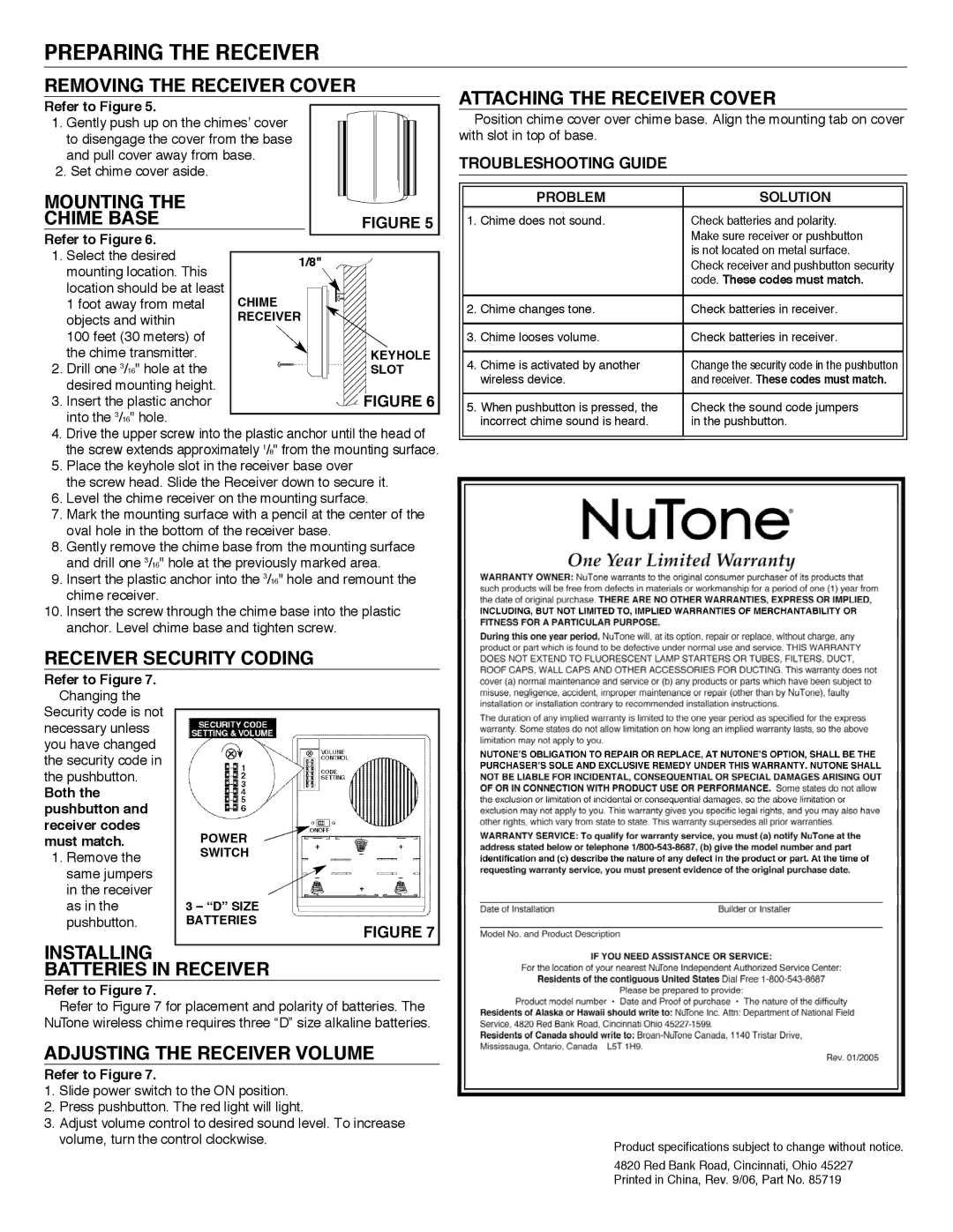
Refer to Figure 6.
1. | Select the desired | 1/8" |
|
|
|
|
|
|
|
| ||||
| mounting location. This |
|
|
|
|
|
|
|
|
|
|
|
|
|
| location should be at least | CHIME |
|
|
|
|
|
|
|
|
|
| ||
| 1 foot away from metal |
|
|
|
|
|
|
|
|
| ||||
|
|
|
|
|
|
|
|
|
|
| ||||
| objects and within | RECEIVER |
|
|
|
|
|
|
|
|
| |||
| 100 feet (30 meters) of |
|
|
|
|
|
|
|
|
|
|
|
|
|
| the chime transmitter. |
|
|
|
|
|
|
|
|
|
|
| KEYHOLE | |
2. | Drill one 3/16" hole at the |
|
|
|
|
|
|
|
|
|
|
| SLOT | |
| desired mounting height. |
|
|
|
|
|
|
|
|
|
|
|
|
|
|
|
|
|
|
|
|
|
|
|
|
|
|
| |
3. | Insert the plastic anchor |
|
|
|
|
|
|
|
|
|
|
| F | IGURE 6 |
|
|
|
|
|
|
|
|
|
|
| ||||
| into the 3/16" hole. |
|
|
|
|
|
|
|
|
|
|
|
|
|
|
|
|
|
|
|
|
|
|
|
|
|
|
| |
4.Drive the upper screw into the plastic anchor until the head of the screw extends approximately 1/8" from the mounting surface.
5.Place the keyhole slot in the receiver base over
the screw head. Slide the Receiver down to secure it.
6.Level the chime receiver on the mounting surface.
7.Mark the mounting surface with a pencil at the center of the oval hole in the bottom of the receiver base.
8.Gently remove the chime base from the mounting surface and drill one 3/16" hole at the previously marked area.
9.Insert the plastic anchor into the 3/16" hole and remount the chime receiver.
10.Insert the screw through the chime base into the plastic anchor. Level chime base and tighten screw.
ATTACHING THE RECEIVER COVER
Position chime cover over chime base. Align the mounting tab on cover with slot in top of base.
TROUBLESHOOTING GUIDE
| PROBLEM | SOLUTION |
1. | Chime does not sound. | Check batteries and polarity. |
|
| Make sure receiver or pushbutton |
|
| is not located on metal surface. |
|
| Check receiver and pushbutton security |
|
| code. These codes must match. |
|
|
|
2. | Chime changes tone. | Check batteries in receiver. |
|
|
|
3. | Chime looses volume. | Check batteries in receiver. |
|
|
|
4. | Chime is activated by another | Change the security code in the pushbutton |
| wireless device. | and receiver. These codes must match. |
|
|
|
5. | When pushbutton is pressed, the | Check the sound code jumpers |
| incorrect chime sound is heard. | in the pushbutton. |
|
|
|
RECEIVER SECURITY CODING
Refer to Figure 7. |
|
Changing the |
|
Security code is not |
|
| |
necessary unless |
|
you have changed |
|
the security code in |
|
the pushbutton. |
|
Both the |
|
pushbutton and |
|
receiver codes | POWER |
must match. | |
1. Remove the | SWITCH |
same jumpers |
|
in the receiver |
|
as in the | 3 – “D” SIZE |
pushbutton . | BATTERIES |
| FIGURE 7 |
INSTALLING
BATTERIES IN RECEIVER
Refer to Figure 7.
Refer to Figure 7 for placement and polarity of batteries. The
NuTone wireless chime requires three “D” size alkaline batteries.
ADJUSTING THE RECEIVER VOLUME
Refer to Figure 7.
1.Slide power switch to the ON position.
2.Press pushbutton. The red light will light.
3.Adjust volume control to desired sound level. To increase
volume, turn the control clockwise. | Product specifications subject to change without notice. |
| |
| 4820 Red Bank Road, Cincinnati, Ohio 45227 |
| Printed in China, Rev. 9/06, Part No. 85719 |