TO
Two-Note Door Chime
•For use with either a transformer or batteries
LOCATION
TRANSFORMER: Mount a
PUSHBUTTON: The chime is designed for
NEW INSTALLATION
INSTALLING TRANSFORMER
Disconnect house power until installation is complete. All wiring must comply with local codes.
1.Use a 16 VOLT, 10 VA transformer.
2.Refer to Figure 1. Mount transformer to a conveniently located junction box. Do not mount transformer in attic.
3.Use approved wire connectors to connect supply wires to transformer leads: white to white; black to black.
WIRES TO CHIME
SUPPLY WIRE
FIGURE 1
REPLACEMENT OR NEW INSTALLATION USING TRANSFORMER
REGISTER THIS PRODUCT, VISIT WWW.NUTONE.COM INSTALLATION INSTRUCTIONS READ & SAVE THESE INSTRUCTIONS!
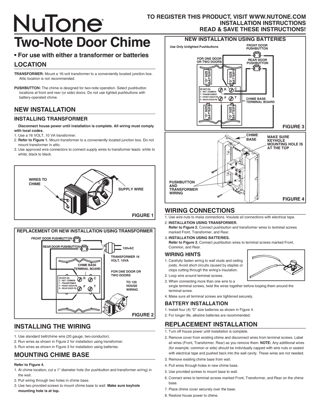
NEW INSTALLATION USING BATTERIES
Use Only Unlighted Pushbuttons |
|
|
| FRONT DOOR | |
|
|
| PUSHBUTTON | ||
|
|
|
| ||
FOR ONE DOOR |
|
|
| REAR DOOR |
|
OR TWO DOORS |
|
|
|
| |
|
|
| PUSHBUTTON | ||
|
|
|
| ||
“D” SIZE BATTERY |
| “D” SIZE | BATTERY |
|
|
DO NOT OIL | R |
| C |
|
|
C - BAT. COMMON |
|
|
|
|
|
T - TRANSFORMER | F |
| T |
|
|
F - FRONT DOOR PB |
| CHIME BASE |
| ||
R - REAR DOOR PB |
|
|
|
| |
|
|
|
| TERMINAL BOARD | |
“D” SIZE BATTERY |
| “D” SIZE | BATTERY |
|
|
|
|
|
|
| FIGURE 3 |
|
|
|
| CHIME | MAKE SURE |
|
|
|
| BASE | |
|
|
|
| KEYHOLE | |
|
|
|
|
| MOUNTING HOLE IS |
|
|
|
|
| AT THE TOP |
PUSHBUTTON
AND
TRANSFORMER
WIRING
FIGURE 4
WIRING CONNECTIONS
1. | Use wire nuts to make connections. Insulate all connections with electrical tape. |
2. | INSTALLATION USING TRANSFORMER. |
| Refer to Figure 2. Connect pushbutton and transformer wires to terminal screws |
| marked Front, Transformer, and Rear. |
FRONT DOOR PUSHBUTTON ![]()
REAR DOOR PUSHBUTTON ![]()
| CHIME BASE | |
TERMINAL BOARD | ||
DO NOT OIL | R | C |
C - BAT. COMMON |
|
|
T - TRANSFORMER |
| T |
F - FRONT DOOR PB | F | |
R - REAR DOOR PB |
|
|
120vAC
TRANSFORMER 16 VOLT, 10VA
FOR ONE DOOR OR TWO DOORS
TO 120
HOUSE
WIRING
3. INSTALLATION USING BATTERIES. |
Refer to Figure 3. Connect pushbutton wires to terminal screws marked Front, |
Common, and Rear. |
WIRING HINTS
1. Carefully fasten wiring to wall studs and ceiling joists. Avoid short circuits caused by staples or clops cutting through the wiring's insulation.
2. Loop wire around terminal screws.
3. When connecting more than one wire to a
single terminal screws, twist the wires together before looping them around the terminal screw.
4. Make sure all terminal screws are tightened securely.
BATTERY INSTALLATION
FIGURE 2
1.Install four (4) “D” size batteries as shown in Figure 4.
2.For longer life, alkaline batteries are recommended.
INSTALLING THE WIRING
1.Use standard bell/chime wire (20 gauge,
2.Run wires as shown in Figure 2 for installation using transformer.
3.Run wires as shown in Figure 3 for installation using batteries.
MOUNTING CHIME BASE
Refer to Figure 4.
1.At chime location, cut a 1" diameter hole (for pushbutton and transformer wiring) in the wall.
2.Pull wiring through two holes in chime base.
3.Use two provided screws to mount chime base to wall. Make sure keyhole mounting hole is at top.
REPLACEMENT INSTALLATION
1.Turn off house power until installation is complete.
2.Remove cover from existing chime and disconnect wires from terminal screws. Label all wires (Front, Transformer, Rear) as you remove them. NOTE: Any additional wires (for example: common or side) should be individually capped with wire nuts or sealed with electrical tape and pushed back into the wall cavity. These wires are not needed.
3.Remove existing chime base from wall.
4.Pull wires through holes in new chime base.
5.Use provided screws to mount base to wall.
6.Connect wires to terminal screws marked Front, Transformer, and Rear on the chime base.
7.Place chime cover securely over the base.
8.Restore house power to chime.