DPG5000 | M3366/0606 |
|
|
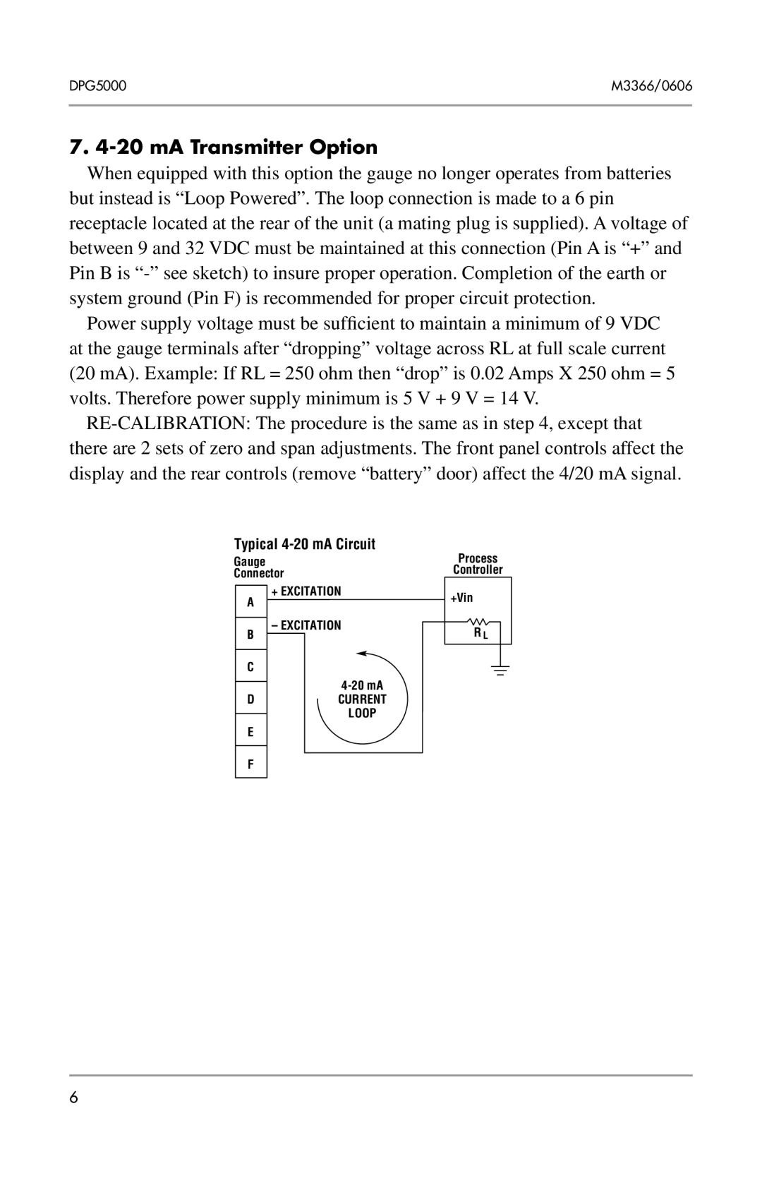
7. 4-20 mA Transmitter Option
When equipped with this option the gauge no longer operates from batteries but instead is “Loop Powered”. The loop connection is made to a 6 pin receptacle located at the rear of the unit (a mating plug is supplied). A voltage of between 9 and 32 VDC must be maintained at this connection (Pin A is “+” and Pin B is
Power supply voltage must be sufficient to maintain a minimum of 9 VDC at the gauge terminals after “dropping” voltage across RL at full scale current (20 mA). Example: If RL = 250 ohm then “drop” is 0.02 Amps X 250 ohm = 5 volts. Therefore power supply minimum is 5 V + 9 V = 14 V.
Typical 4-20 mA Circuit
Gauge |
| Process |
Connector | Controller | |
| ||
A | + EXCITATION | +Vin |
| ||
|
| |
B | – EXCITATION | R L |
| ||
C
DCURRENT
LOOP
E
F