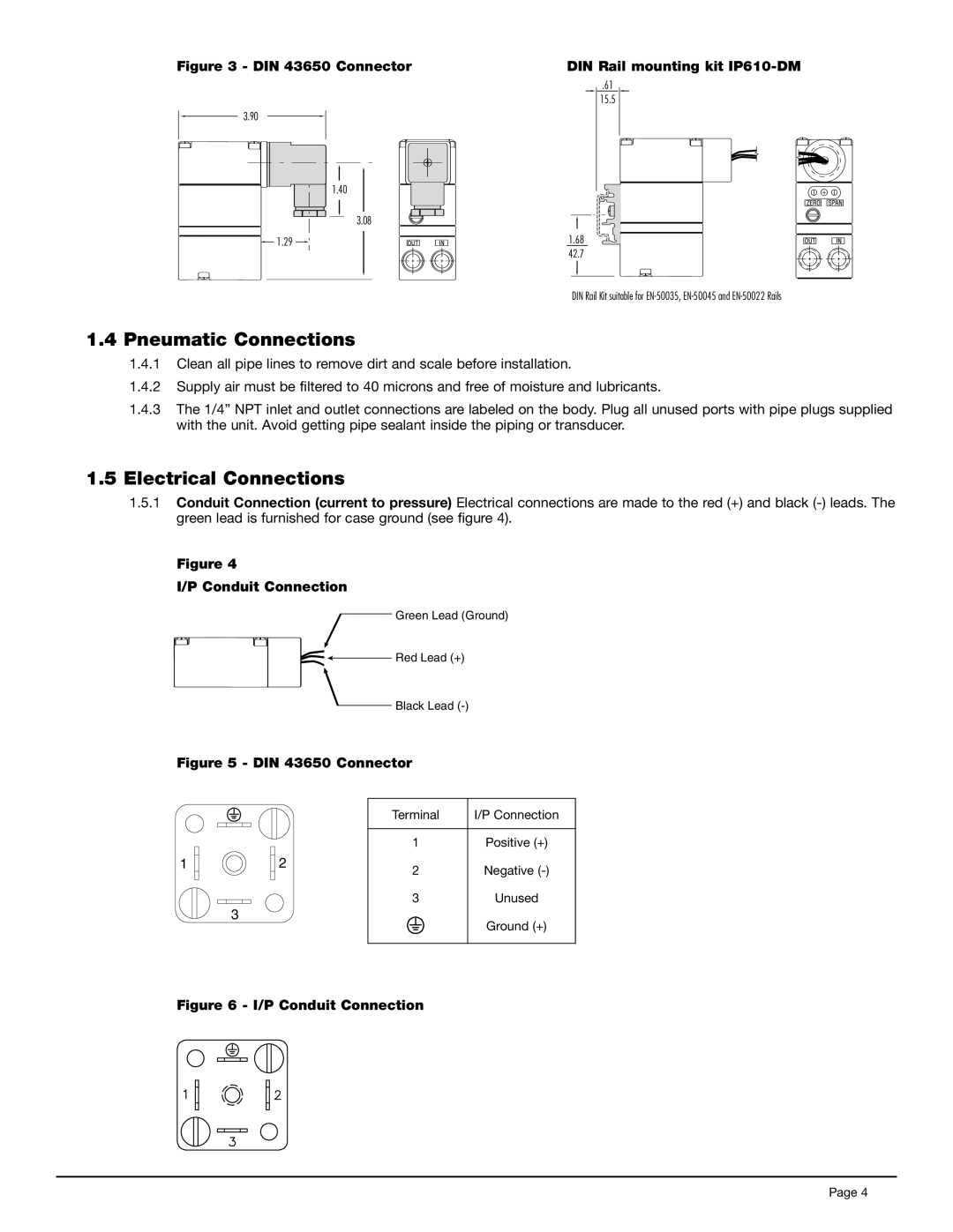
Figure 3 - DIN 43650 Connector
3.90
1.40
3.08
![]() 1.29
1.29 ![]()
1.4 Pneumatic Connections
DIN Rail mounting kit IP610-DM
.61
15.5
1.68
42.7
DIN Rail Kit suitable for
1.4.1Clean all pipe lines to remove dirt and scale before installation.
1.4.2Supply air must be filtered to 40 microns and free of moisture and lubricants.
1.4.3The 1/4” NPT inlet and outlet connections are labeled on the body. Plug all unused ports with pipe plugs supplied with the unit. Avoid getting pipe sealant inside the piping or transducer.
1.5Electrical Connections
1.5.1Conduit Connection (current to pressure) Electrical connections are made to the red (+) and black
Figure 4
I/P Conduit Connection
Green Lead (Ground)
![]()
![]() Red Lead (+)
Red Lead (+)
Black Lead
Figure 5 - DIN 43650 Connector
1
2
3
Terminal | I/P Connection |
1Positive (+)
2Negative
3Unused
Ground (+)
Figure 6 - I/P Conduit Connection
Page 4