1.6Factory Mutual Research Corporation (FM) and Canadian Standards association (CSA)
Intrinsically Safe | Suitable for: |
Class I, II, III, Div. 1, | Class I, Div. 2, Groups A, B, C & D |
Groups C, D, E, F & G | Models |
Models | |
Class I, Div. 1, Groups C & D |
|
Models |
|
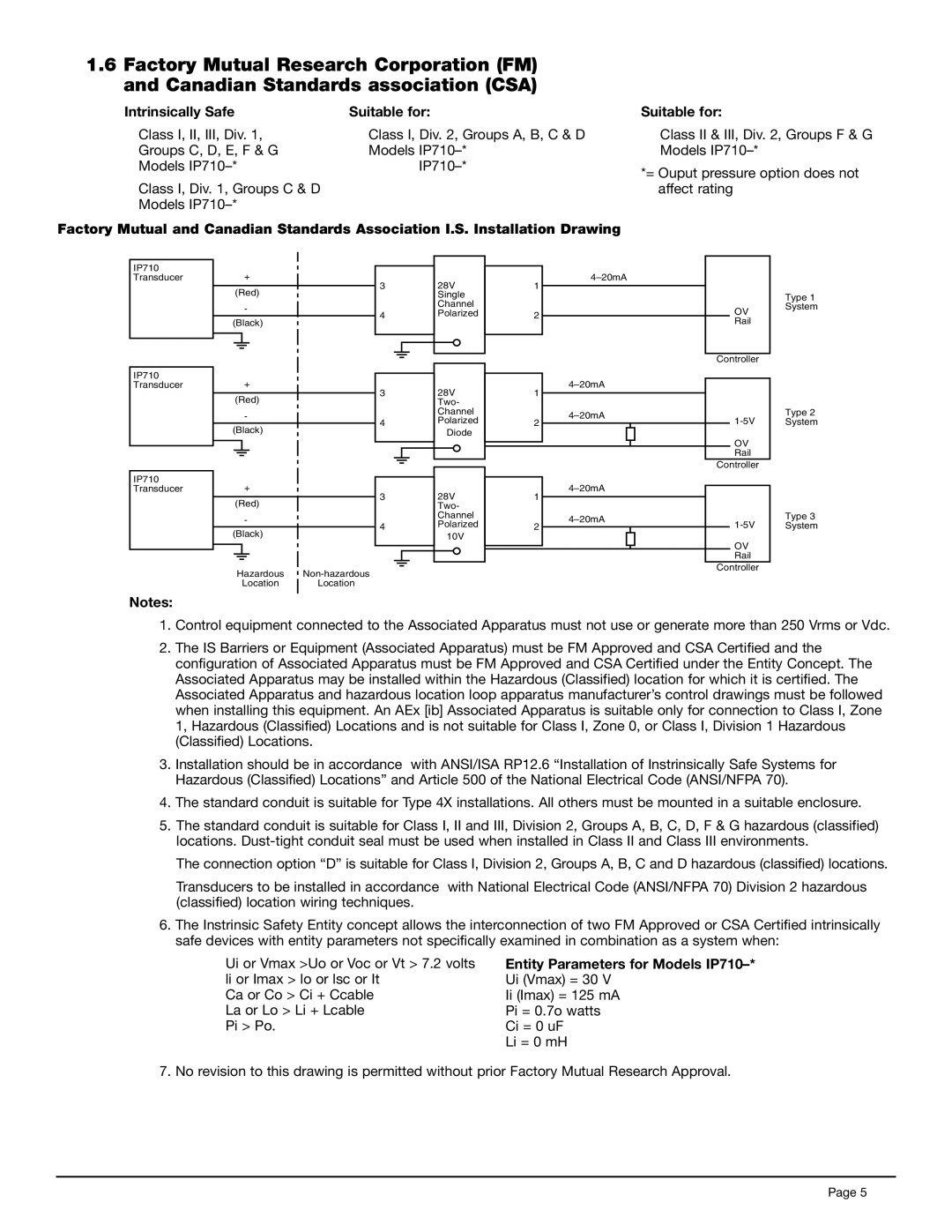
Factory Mutual and Canadian Standards Association I.S. Installation Drawing
Suitable for:
Class II & III, Div. 2, Groups F & G Models
*= Ouput pressure option does not affect rating
IP710 Transducer
IP710 Transducer
IP710 Transducer
Notes:
+
(Red)
-
(Black)
+
(Red)
-
(Black)
+
(Red)
-
(Black)
Hazardous
Location Location
3
4
3
4
3
4
28V Single Channel Polarized
28V Two- Channel Polarized
Diode
28V Two- Channel Polarized
10V
1
2
1
2
1
2
| Type 1 | |
OV | System | |
| ||
Rail |
| |
|
| |
Controller |
| |
| Type 2 | |
System | ||
OV |
| |
Rail |
| |
Controller |
| |
| Type 3 | |
System | ||
OV |
| |
Rail |
| |
Controller |
|
1.Control equipment connected to the Associated Apparatus must not use or generate more than 250 Vrms or Vdc.
2.The IS Barriers or Equipment (Associated Apparatus) must be FM Approved and CSA Certified and the configuration of Associated Apparatus must be FM Approved and CSA Certified under the Entity Concept. The Associated Apparatus may be installed within the Hazardous (Classified) location for which it is certified. The Associated Apparatus and hazardous location loop apparatus manufacturer’s control drawings must be followed when installing this equipment. An AEx [ib] Associated Apparatus is suitable only for connection to Class I, Zone 1, Hazardous (Classified) Locations and is not suitable for Class I, Zone 0, or Class I, Division 1 Hazardous (Classified) Locations.
3.Installation should be in accordance with ANSI/ISA RP12.6 “Installation of Instrinsically Safe Systems for Hazardous (Classified) Locations” and Article 500 of the National Electrical Code (ANSI/NFPA 70).
4.The standard conduit is suitable for Type 4X installations. All others must be mounted in a suitable enclosure.
5.The standard conduit is suitable for Class I, II and III, Division 2, Groups A, B, C, D, F & G hazardous (classified) locations.
The connection option “D” is suitable for Class I, Division 2, Groups A, B, C and D hazardous (classified) locations.
Transducers to be installed in accordance with National Electrical Code (ANSI/NFPA 70) Division 2 hazardous (classified) location wiring techniques.
6.The Instrinsic Safety Entity concept allows the interconnection of two FM Approved or CSA Certified intrinsically safe devices with entity parameters not specifically examined in combination as a system when:
Ui or Vmax >Uo or Voc or Vt > 7.2 volts li or Imax > lo or lsc or It
Ca or Co > Ci + Ccable La or Lo > Li + Lcable Pi > Po.
Entity Parameters for Models IP710–* Ui (Vmax) = 30 V
Ii (Imax) = 125 mA
Pi = 0.7o watts
Ci = 0 uF
Li = 0 mH
7. No revision to this drawing is permitted without prior Factory Mutual Research Approval.
Page 5