OM-USB-1208FS specifications
The Omega OM-USB-1208FS is a high-performance data acquisition device designed for engineers and technicians who require accurate data logging and analysis in their experiments and applications. This versatile device is equipped with a range of features that make it an ideal choice for various measurement tasks across different industries.One of the standout features of the OM-USB-1208FS is its ability to support a wide variety of input signals. The device is equipped with 16 analog input channels, which can be used for both voltage and thermocouple inputs, making it suitable for temperature monitoring and other signal measurements. The analog inputs provide a resolution of 16 bits, ensuring precise and reliable readings. Furthermore, it supports sampling rates of up to 100 kS/s, allowing for rapid data acquisition and real-time monitoring.
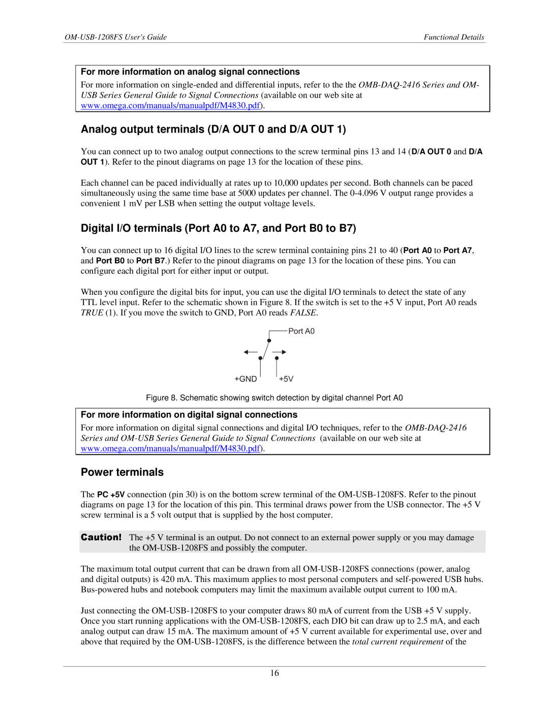
In addition to its analog capabilities, the OM-USB-1208FS has digital I/O lines that facilitate control and automation tasks. With 8 digital input/output channels, users can easily manage various external devices, sensors, or actuators, enhancing the overall functionality of the data acquisition system. This makes the device suitable for automation projects, as users can trigger actions based on acquired data.
Another distinguishing feature is the built-in USB interface, which offers a straightforward connection to computers without the need for additional power supplies or complex setups. The device is fully compatible with various operating systems, including Windows, making it easy to integrate into existing systems. The included software allows for easy data logging, visualization, and analysis, simplifying the process for users.
The OM-USB-1208FS is designed with durability and reliability in mind. Its compact and rugged construction ensures that it can withstand the rigors of fieldwork and laboratory use. Moreover, the device's comprehensive range of input types and robust performance specifications make it an asset for researchers across diverse fields, including environmental monitoring, manufacturing, and academic research.
In summary, the Omega OM-USB-1208FS is a powerful data acquisition solution that combines a multitude of features and technologies. With its high-resolution analog inputs, digital I/O capabilities, user-friendly USB interface, and reliable construction, it caters to the diverse needs of professionals seeking to capture and analyze data accurately and efficiently. Whether for academic research, industrial applications, or environmental monitoring, the OM-USB-1208FS stands out as a top choice in the data acquisition landscape.

