Manuals
/
Omega
/
Personal Care
/
Thermometer
Omega
manual
Assembly of the TX91 Transmitter Inside
Models:
TX91
1
16
36
36
Download
36 pages
42.8 Kb
13
14
15
16
17
18
19
20
Troubleshooting
Specs
Install
Warranty
Accessories
Features
Page 16
Image 16
3
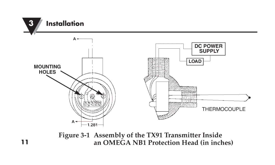
Installation
MOUNTING
HOLES
DC POWER
SUPPLY
LOAD
THERMOCOUPLE
11
Figure
3-1
Assembly of the TX91 Transmitter Inside
an OMEGA NB1 Protection Head (in inches)
Page 15
Page 17
Page 16
Image 16
Page 15
Page 17
Contents
User’sGuide
Servicing North America
Return Requests / Inquiries
Introduction
Calibration Instructions
Introduction
General Description
Introduction
TX91 Thermocouple Transmitter
Introduction
Introduction
Straight line Approximation of Curve
Features
Models Available
TX91 Models Available Model Number Description
Unpacking
Installation
Mounting the TX91
Assembly of the TX91 Transmitter Inside
RT Mounting Track in inches
TX90-BR Mounting Bracket in inches
Mounting Track RT Bracket TX90-BR
Wiring the TX91 Refer to Figure
Wiring Diagram for the TX91 Potentiometers
Calibration Instructions
Equipment Required
Set-up of Equipment
Calibration Procedures Refer to Figure
Calibration Instructions
Calibration Set-Up
Calibration Set-Up. Alternate
Calibration Values for the TX92
Troubleshooting Guide
Current rating on the power supply
Troubleshooting Guide
Accessories
Model No Description
Specifications
General
Input
Intrinsically Safe Interconnection Diagram
WARRANTY/DISCLAIMER
Shop online at omega.com
Top
Page
Image
Contents