5.5Interrupt Mode Control Register (Base + 6)
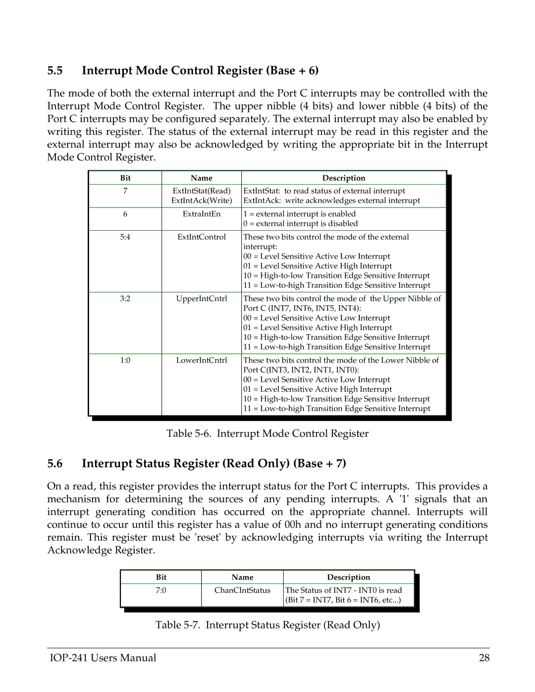
The mode of both the external interrupt and the Port C interrupts may be controlled with the Interrupt Mode Control Register. The upper nibble (4 bits) and lower nibble (4 bits) of the Port C interrupts may be configured separately. The external interrupt may also be enabled by writing this register. The status of the external interrupt may be read in this register and the external interrupt may also be acknowledged by writing the appropriate bit in the Interrupt Mode Control Register.
| Bit | Name |
| Description |
|
|
|
| |||
|
|
|
|
| |
| 7 | ExtIntStat(Read) | ExtIntStat: to read status of external interrupt |
| |
|
| ExtIntAck(Write) | ExtIntAck: write acknowledges external interrupt |
| |
|
|
|
|
| |
| 6 | ExtraIntEn | 1 = external interrupt is enabled |
| |
|
|
| 0 = external interrupt is disabled |
| |
|
|
|
|
| |
| 5:4 | ExtIntControl | These two bits control the mode of the external |
| |
|
|
| interrupt: |
| |
|
|
| 00 | = Level Sensitive Active Low Interrupt |
|
|
|
| 01 | = Level Sensitive Active High Interrupt |
|
|
|
| 10 | = |
|
|
|
| 11 | = |
|
|
|
|
|
| |
| 3:2 | UpperIntCntrl | These two bits control the mode of the Upper Nibble of |
| |
|
|
| Port C (INT7, INT6, INT5, INT4): |
| |
|
|
| 00 | = Level Sensitive Active Low Interrupt |
|
|
|
| 01 | = Level Sensitive Active High Interrupt |
|
|
|
| 10 | = |
|
|
|
| 11 | = |
|
|
|
|
|
| |
| 1:0 | LowerIntCntrl | These two bits control the mode of the Lower Nibble of |
| |
|
|
| Port C(INT3, INT2, INT1, INT0): |
| |
|
|
| 00 | = Level Sensitive Active Low Interrupt |
|
|
|
| 01 | = Level Sensitive Active High Interrupt |
|
|
|
| 10 | = |
|
|
|
| 11 | = |
|
|
|
|
|
|
|
|
|
|
|
|
|
Table
5.6Interrupt Status Register (Read Only) (Base + 7)
On a read, this register provides the interrupt status for the Port C interrupts. This provides a mechanism for determining the sources of any pending interrupts. A '1' signals that an interrupt generating condition has occurred on the appropriate channel. Interrupts will continue to occur until this register has a value of 00h and no interrupt generating conditions remain. This register must be 'reset' by acknowledging interrupts via writing the Interrupt Acknowledge Register.
| Bit | Name | Description |
|
|
| |||
|
|
|
|
|
| 7:0 | ChanCIntStatus | The Status of INT7 - INT0 is read |
|
|
|
| (Bit 7 = INT7, Bit 6 = INT6, etc...) |
|
|
|
|
|
|
|
|
|
|
|
Table
28 |
