WIRING

Step Four

Follow the instructions in Step 3 for wiring to the LVU-90.

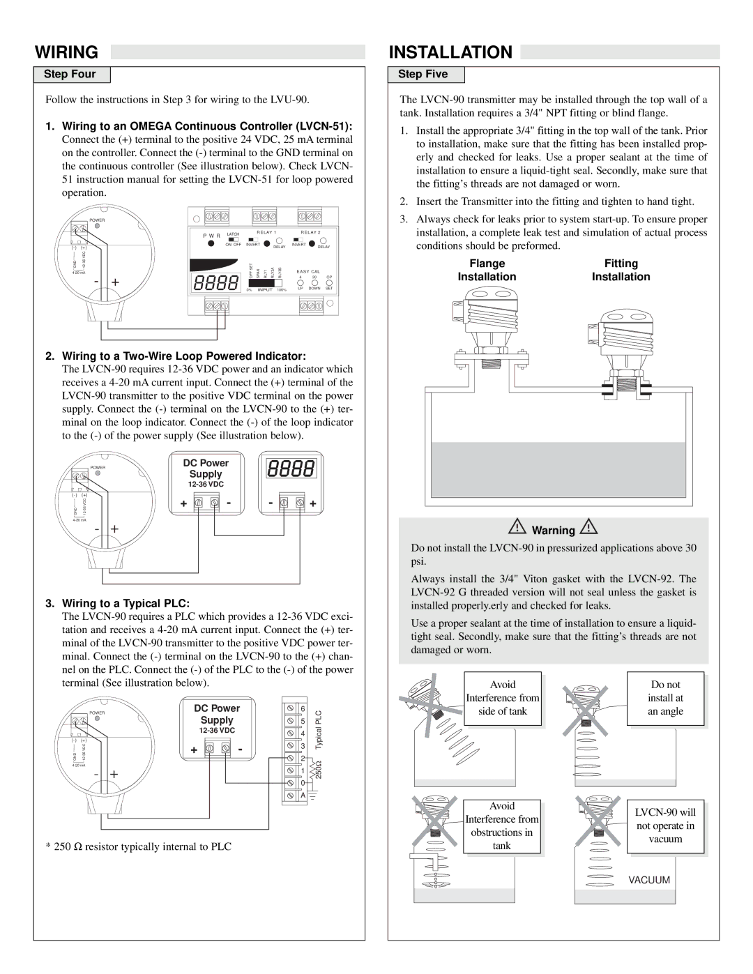
1.Wiring to an OMEGA Continuous Controller (LVCN-51):

Connect the (+) terminal to the positive 24 VDC, 25 mA terminal on the controller. Connect the (-) terminal to the GND terminal on the continuous controller (See illustration below). Check LVCN- 51 instruction manual for setting the LVCN-51 for loop powered operation.

INSTALLATION

Step Five

The LVCN-90 transmitter may be installed through the top wall of a tank. Installation requires a 3/4" NPT fitting or blind flange.

1.

Install the appropriate 3/4" fitting in the top wall of the tank. Prior


to installation, make sure that the fitting has been installed prop-


erly and checked for leaks. Use a proper sealant at the time of


installation to ensure a liquid-tight seal. Secondly, make sure that


the fitting’s threads are not damaged or worn.

2.

Insert the Transmitter into the fitting and tighten to hand tight.


POWER

(-)

(+)

GND

12-36 VDC

4-20 mA

- +

P W R

LATCH


R E L AY 1


R E L AY 2


ON OFF

INVERT


DELAY

INVERT

DELAY


OFF SET

SPAN

RLY1

RLY2A

RLY2B

E A S Y CAL


4

20

OP


0%

INPUT

100%

UP

DOWN

SET

3. Always check for leaks prior to system start-up. To ensure proper

installation, a complete leak test and simulation of actual process

conditions should be preformed.

FlangeFitting

InstallationInstallation

2.Wiring to a Two-Wire Loop Powered Indicator:

The LVCN-90 requires 12-36 VDC power and an indicator which receives a 4-20 mA current input. Connect the (+) terminal of the LVCN-90 transmitter to the positive VDC terminal on the power supply. Connect the (-) terminal on the LVCN-90 to the (+) ter- minal on the loop indicator. Connect the (-) of the loop indicator to the (-) of the power supply (See illustration below).


POWER

DC Power


Supply


12-36 VDC


(-)

(+)

+

-

-

+


VDC

GND

12-36


4-20 mA

+


-


3.Wiring to a Typical PLC:

The LVCN-90 requires a PLC which provides a 12-36 VDC exci- tation and receives a 4-20 mA current input. Connect the (+) ter- minal of the LVCN-90 transmitter to the positive VDC power ter- minal. Connect the (-) terminal on the LVCN-90 to the (+) chan- nel on the PLC. Connect the (-) of the PLC to the (-) of the power terminal (See illustration below).


POWER

DC Power

6

PLC


VDC

Supply


5


12-36 VDC


3

Typical

(-)

(+)


4


+

-


GND

12-36

2


+


250Ω


-


4-20 mA


1


0


A


* 250 Ω resistor typically internal to PLC


Warning

Do not install the LVCN-90 in pressurized applications above 30 psi.

Always install the 3/4" Viton gasket with the LVCN-92. The LVCN-92 G threaded version will not seal unless the gasket is installed properly.erly and checked for leaks.

Use a proper sealant at the time of installation to ensure a liquid- tight seal. Secondly, make sure that the fitting’s threads are not damaged or worn.

Avoid

Do not

Interference from

install at

side of tank

an angle

Avoid

LVCN-90 will

Interference from

not operate in

obstructions in

vacuum

tank


VACUUM

Page 4
Image 4
Omega Engineering LVU-90 warranty Installation, Step Four, Wiring to an Omega Continuous Controller LVCN-51, Step Five

LVU-90 specifications

Omega Engineering has long been a leader in providing innovative solutions for temperature and process measurement, and one of its standout products is the LVU-90 Liquid Level Transmitter. This device is designed to offer reliable and accurate liquid level measurement in a variety of industrial applications. The LVU-90 leverages advanced technologies to ensure precision while maintaining versatility across different environments.

One of the main features of the LVU-90 is its non-contact measurement capability. This characteristic allows the transmitter to determine liquid levels without needing to make physical contact with the liquid itself. This is particularly advantageous in applications involving corrosive or hazardous materials, where traditional contact measurement methods may pose risks or lead to deterioration over time. The non-contact design also reduces maintenance requirements, ultimately increasing operational efficiency.

Another notable feature of the LVU-90 is its ability to operate in a wide temperature range. The device is designed to function in both extreme heat and cold, providing versatility for various industrial settings. This robust temperature tolerance ensures that the LVU-90 can be employed in diverse applications, from water and wastewater management to chemical processing and agriculture.

The LVU-90 utilizes advanced ultrasonic technology for its measurement process. By emitting ultrasonic waves from the transmitter, it measures the time taken for the waves to travel to the surface of the liquid and back, allowing for highly accurate level readings. The utilization of this technology minimizes the influence of factors such as temperature or pressure variations, resulting in dependable performance under differing operational conditions.

Additionally, the LVU-90 is equipped with a user-friendly interface that simplifies setup and provides clear diagnostic information. Its integration capabilities allow for seamless connectivity with existing control systems, enabling real-time monitoring and enhancing overall process management.

The LVU-90 also features a durable construction, designed to withstand harsh environments. This robustness ensures longevity and reduces replacement frequency, offering significant cost savings over time. With its combination of cutting-edge technology, ease of use, and resilience, the Omega Engineering LVU-90 Liquid Level Transmitter emerges as a superior choice for industries seeking reliable liquid level measurement solutions.