® ![]()
PSW400
Pressure Switches
INSTRUCTION | M0534/0902 | |
SHEET | ||
|
INSTALLATION INSTRUCTIONS FOR OMEGA®
SERIES PSW400 PRESSURE SWITCHES
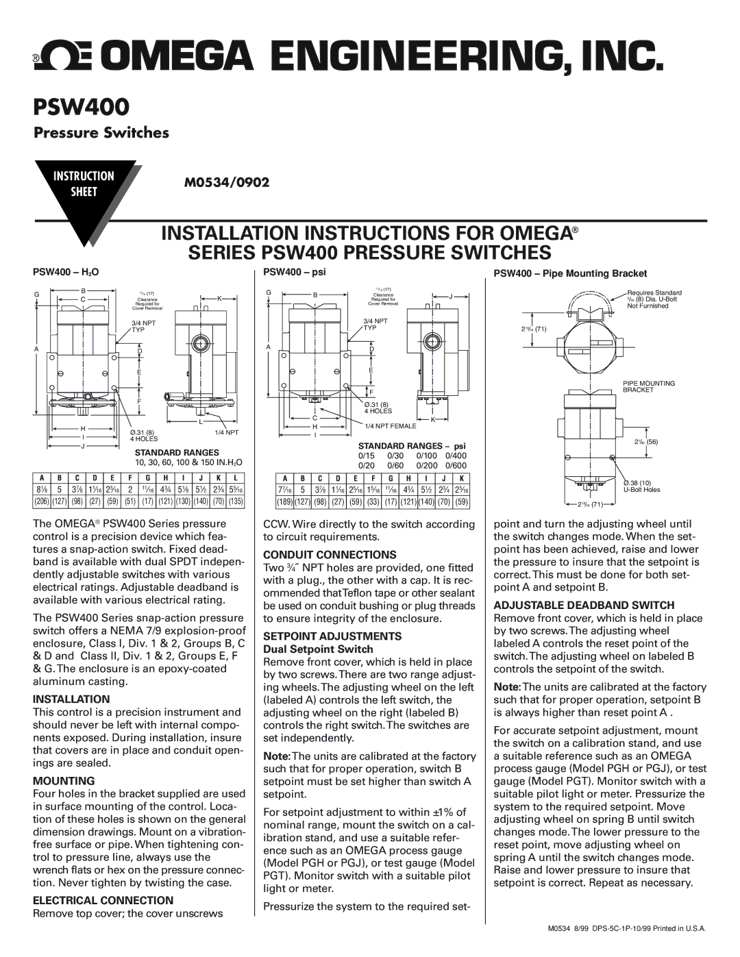
PSW400 – H2O
G | B | 11/16 (17) | K | |
C | Clearance | |||
| ||||
|
| Required for |
| |
|
| Cover Removal |
| |
|
| 3/4 NPT |
| |
|
| TYP |
| |
A |
| D |
| |
|
|
|
E
|
| L | |
| F |
| |
H |
| L | |
Ø.31 (8) | 1/4 NPT | ||
I | |||
4 HOLES |
| ||
J |
|
|
STANDARD RANGES
10, 30, 60, 100 & 150 IN.H2O
A | B | C | D | E | F | G | H | I | J | K | L |
81⁄8 | 5 | 37⁄8 | 11⁄16 | 25⁄16 | 2 | 11⁄16 | 43⁄4 | 51⁄8 | 51⁄2 | 23⁄4 | 55⁄16 |
(206) | (127) | (98) | (27) | (59) | (51) | (17) | (121) | (130) | (140) | (70) | (135) |
|
|
|
|
|
|
|
|
|
|
|
|
The OMEGA® PSW400 Series pressure control is a precision device which fea- tures a
The PSW400 Series
&D and Class II, Div. 1 & 2, Groups E, F
&G.The enclosure is an
INSTALLATION
This control is a precision instrument and should never be left with internal compo- nents exposed. During installation, insure that covers are in place and conduit open- ings are sealed.
MOUNTING
Four holes in the bracket supplied are used in surface mounting of the control. Loca- tion of these holes is shown on the general dimension drawings. Mount on a vibration- free surface or pipe. When tightening con- trol to pressure line, always use the wrench flats or hex on the pressure connec- tion. Never tighten by twisting the case.
ELECTRICAL CONNECTION
Remove top cover; the cover unscrews
PSW400 – psi
G | B | 11/16 (17) |
|
Clearance | J | ||
| Required for | ||
|
| Cover Removal |
|
|
| 3/4 NPT |
|
|
| TYP |
|
A |
| D |
|
|
|
|
E
| F |
| Ø.31 (8) |
C | 4 HOLES |
K | |
H | 1/4 NPT FEMALE |
I |
|
|
|
|
| STANDARD RANGES – psi | ||||||||
|
|
|
| 0/15 | 0/30 | 0/100 | 0/400 | |||||
|
|
|
| 0/20 | 0/60 | 0/200 | 0/600 | |||||
|
|
|
|
|
|
|
|
|
|
|
|
|
A | B | C | D | E | F | G | H |
| I |
| J | K |
77⁄16 | 5 | 37⁄8 | 11⁄16 | 25⁄16 | 15⁄16 | 11⁄16 | 43⁄4 | 51⁄2 | 23⁄4 | 25⁄16 | ||
(189) | (127) | (98) | (27) | (59) | (33) | (17) | (121) | (140) | (70) | (59) | ||
|
|
|
|
|
|
|
|
|
|
|
|
|
CCW. Wire directly to the switch according to circuit requirements.
CONDUIT CONNECTIONS
Two 3⁄4˝ NPT holes are provided, one fitted with a plug., the other with a cap. It is rec- ommended thatTeflon tape or other sealant be used on conduit bushing or plug threads to ensure integrity of the enclosure.
SETPOINT ADJUSTMENTS
Dual Setpoint Switch
Remove front cover, which is held in place by two screws.There are two range adjust- ing wheels.The adjusting wheel on the left (labeled A) controls the left switch, the adjusting wheel on the right (labeled B) controls the right switch.The switches are set independently.
Note:The units are calibrated at the factory such that for proper operation, switch B setpoint must be set higher than switch A setpoint.
For setpoint adjustment to within ±1% of nominal range, mount the switch on a cal- ibration stand, and use a suitable refer- ence such as an OMEGA process gauge (Model PGH or PGJ), or test gauge (Model PGT). Monitor switch with a suitable pilot light or meter.
Pressurize the system to the required set-
PSW400 – Pipe Mounting Bracket
Requires Standard
5/16 (8) Dia.
Not Furnished
213/16 (71)
PIPE MOUNTING
BRACKET
27/32 (56)
Ø.38 (10)
![]() 213/16 (71)
213/16 (71)![]()
point and turn the adjusting wheel until the switch changes mode. When the set- point has been achieved, raise and lower the pressure to insure that the setpoint is correct.This must be done for both set- point A and setpoint B.
ADJUSTABLE DEADBAND SWITCH Remove front cover, which is held in place by two screws.The adjusting wheel labeled A controls the reset point of the switch.The adjusting wheel on labeled B controls the setpoint of the switch.
Note:The units are calibrated at the factory such that for proper operation, setpoint B is always higher than reset point A .
For accurate setpoint adjustment, mount the switch on a calibration stand, and use a suitable reference such as an OMEGA process gauge (Model PGH or PGJ), or test gauge (Model PGT). Monitor switch with a suitable pilot light or meter. Pressurize the system to the required setpoint. Move adjusting wheel on spring B until switch changes mode.The lower pressure to the reset point, move adjusting wheel on spring A until the switch changes mode. Raise and lower pressure to insure that setpoint is correct. Repeat as necessary.
M0534 8/99