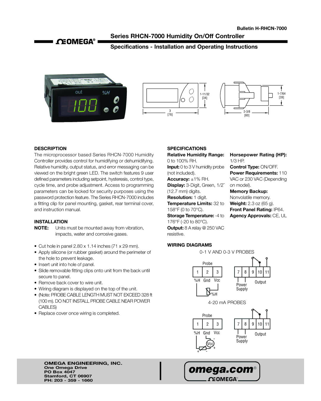
RHCN-7000 specifications
The Omega Engineering RHCN-7000 is a cutting-edge temperature and humidity data logger designed for precise environmental monitoring in various applications. This robust device integrates advanced technologies, making it an essential tool for research laboratories, manufacturing environments, and HVAC applications where accurate readings are critical.One of the standout features of the RHCN-7000 is its multifunctionality. It combines temperature and humidity measurements into a single compact unit, allowing users to monitor both parameters simultaneously. This dual capability helps streamline data collection processes and provides a comprehensive overview of environmental conditions.
Equipped with high-precision sensors, the RHCN-7000 delivers exceptional accuracy in temperature and humidity measurements. The temperature range typically spans from -40°C to 85°C, while the humidity range extends from 0% to 100% relative humidity. This wide measurement range ensures versatility across various operational environments, from cold storage facilities to high-humidity industrial settings.
The RHCN-7000 features a user-friendly interface with a large, backlit LCD display that shows real-time data readings. Users can easily navigate through menus to review historical data and access settings, ensuring that the device is straightforward to operate, even for those who may not be technically inclined.
Another significant advantage of the RHCN-7000 is its advanced data logging capabilities. It allows for extensive memory storage, enabling continuous data logging over extended periods. Users can set their desired logging intervals, ensuring they capture the data necessary for compliance, analysis, or research purposes.
Connectivity is another area where the RHCN-7000 excels. It supports various communication protocols, including USB and wireless options, enabling seamless data transfer to computers and cloud platforms. This feature facilitates real-time monitoring and remote access to data, enhancing productivity and operational efficiency.
Robust build quality is a defining trait of the RHCN-7000. Designed to withstand challenging conditions, it boasts a durable housing that protects against dust and moisture, ensuring reliable performance in various environments. Additionally, its lightweight design makes it easy to deploy and transport as needed.
In summary, the Omega Engineering RHCN-7000 stands out for its high-accuracy measurements, multifunctionality, user-friendly interface, extensive logging capabilities, and robust construction. These characteristics make it an indispensable tool for anyone needing reliable temperature and humidity data in diverse applications.

