SBG22445, SBG25872, SBG25873 (Non-Latching), SBG41705 (Latching) Solid-State Relays

for Intrinsic Safety Use Instruction Sheet M1773/0794

DESCRIPTION

The OMEGA® SBG22445, SBG25872, SBG25873 and SBG41705 Solid- State Relays are used as "intrinsically safe switching circuits in hazardous locations, with non-voltage- producing sensors. When installed in accor- dance with this manual, these field sensors are suitable for Class I, Division 1, 2, Groups A, B, C and D, and Class II, Division 2, Groups E, F and G as defined by Article 500 of the National Electric Code.

UNPACKING

Remove the Packing List and verify that you have received all equipment. If you have any questions about the shipment, please call the OMEGA Customer Service Department at 1-800-622-2378 or (203) 359-1660. When you receive the shipment, inspect the container and equipment for any signs of damage. Note any evidence of rough handling in transit. Immediately report any damage to the shipping agent.

NOTE

The carrier will not honor any claims unless all shipping material is saved for their examination. After examining and removing contents, save packaging material and carton in the event reshipment is necessary.

Important: Read carefully and completely before installing or connecting the solid-state relays.

ASSOCIATED EQUIPMENT

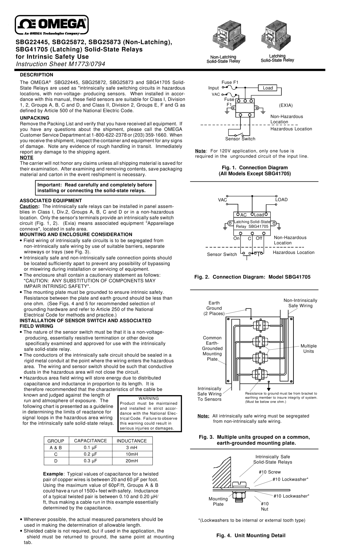
Caution: The intrinsically safe relays can be installed in panel assem- blies in Class I, Div.2, Groups A, B, C and D or in a non-hazardous location. Only the sensor's terminals provide an intrinsically safe switch circuit (Fig. 1, 2). (Exia) means associated equipment "Appareilage connexe", located in safe area.

MOUNTING AND ENCLOSURE CONSIDERATION

Field wiring of intrinsically safe circuits is to be segregated from

non-intrinsically safe wiring by use of suitable barriers, separate

wireways or trays (see Fig. 3).

Intrinsically safe and non-intrinsically safe connection points should

be located sufficiently apart to prevent any possibility of bypassing

or miswiring during installation or servicing of equipment.

The enclosure shall contain a cautionary statement as follows:

"CAUTION: ANY SUBSTITUTION OF COMPONENTS MAY

IMPAIR INTRINSIC SAFETY".

The mounting plate must be grounded to ensure intrinsic safety.

Resistance between the plate and earth ground should be less than

Fuse F1

InputLoad

VAC

Fuse

F1(EXIA)

Non-Hazardous

Location

Hazardous Location

Sensor Switch

Note: For 120V application, only one fuse is required in the ungrounded circuit of the input line.

Fig. 1. Connection Diagram

(All Models Except SBG41705)

VACLOAD

AC Load

Latching Solid-State

Relay SBG41705

On C Off Non-Hazardous

Location

Sensor Switch

Hazardous Location


Fig. 2. Connection Diagram: Model SBG41705

one ohm. (See Figs. 4 and 5 for recommended selection of

grounding hardware and refer to Article 250 of the National Electrical Code for methods and practice.)

INSTALLATION OF SENSOR SWITCH AND ASSOCIATED FIELD WIRING

The nature of the sensor switch must be that it is a non-voltage-

producing, essentially resistive termination or other device specifically examined and approved for use with the intrinsically safe solid-state relay.

The conductors of the intrinsically safe circuit should be sealed in a rigid metal conduit at the point where the wiring enters the hazardous area. The wiring and sensor switch should be such that conductive dusts in the hazardous area will not close the circuit.

Hazardous area field wiring will store energy due to distributed capacitance and inductance in proportion to its length. It is

therefore recommended that the characteristics of the cable be known and judged against the length of

run and atmosphere of exposure. TheWARNING Product must be maintained

following chart is presented as a guideline and installed in strict accor- in determining the limits of reactance for dance with the National Elec-

Earth

Ground

(2 Places)

Common

Earth-

Grounded

Mounting

Plate

Intrinsically

Safe Wiring

To Sensors

Non-Intrinsically

Safe Wiring

Multiple

Units

Resistance to ground must be from bracket to earthing member to insure integrity of system. (Must be below one ohm.)

signal loops in the hazardous area wiring trical Code. Failure to observe for the intrinsically safe solid-state relays. this warning could result in

serious injuries or damages.

Note: All intrinsically safe wiring must be segregated from non-intrinsically safe wiring.

GROUP

CAPACITANCE

INDUCTANCE

A & B

0.1 µF

3 mH


C

0.2 µF

10mH

D

0.3 µF

20mH


Example: Typical values of capacitance for a twisted pair of copper wires is between 20 and 60 pF per foot. Using the maximum value of 60pF/ft, Groups A & B could have a run of 1500+ feet with safety. Inductance

Fig. 3. Multiple units grouped on a common, earth-grounded mounting plate.

Intrinsically Safe

Solid-State Relays

#10 Screw

#10 Lockwasher*

of a typical twisted pair is between 0.10 and 0.20 µH/ ft, thus making a cable run in this example essentially

Mounting

#10 Lockwasher*

determined by the capacitance.

Whenever possible, the actual measured parameters should be used in making the determination of allowable length.

Shielded cable is not required, but if used in the application, the

shield must be returned to ground, the same point at mounting tab.

Plate#10

Nut

*(Lockwashers to be internal or external tooth type)

Fig. 4. Unit Mounting Detail

Page 1
Image 1
Omega Engineering SBG41705, SBG25873, SBG22445, SBG25872 instruction sheet Description, Unpacking

SBG25873, SBG41705, SBG25872, SBG22445 specifications

Omega Engineering is a well-known name in the field of industrial measurement and control instrumentation, and their SBG series of products showcases the company's commitment to quality and innovation. The SBG22445, SBG25872, SBG41705, and SBG25873 are distinct models within the SBG line, each engineered to address specific measurement challenges while delivering exceptional accuracy and reliability.

The SBG22445 model is typically designed for high-performance temperature measurement, utilizing advanced thermocouple technology. It can operate over a broad temperature range, making it suitable for various industrial applications. With its digital display and user-friendly interface, this device allows for quick readings and easy calibration, ensuring that users can monitor temperature fluctuations in real-time.

Moving on to the SBG25872 model, this device specializes in humidity and temperature measurement. It integrates sophisticated sensors that combine precision with a rapid response time, ideal for environments where humidity and temperature conditions fluctuate frequently. The built-in data logging features allow for the collection of historical data, enabling users to analyze trends and ensure optimal conditions for processes sensitive to environmental changes.

The SBG41705 is tailored for pressure measurement, bringing advanced piezoresistive technology into play. This model is particularly useful in applications requiring accurate and continuous pressure monitoring. Equipped with a robust housing and protection from external elements, the SBG41705 excels in harsh industrial environments, providing reliable performance even under challenging conditions.

Lastly, the SBG25873 serves as a multifunctional device capable of measuring various parameters, including temperature, pressure, and humidity. This versatility makes it an invaluable asset in industrial settings where monitoring multiple variables is crucial for operational efficiency. Its user-friendly interface and extensive connectivity options enable seamless integration into existing systems, further enhancing its utility.

In summary, the Omega Engineering SBG series, represented by models like the SBG22445, SBG25872, SBG41705, and SBG25873, reflects the company's dedication to precision measurement. Their innovative use of advanced technologies and durable construction makes them indispensable tools in various industrial and research applications. Users can rely on these devices not only for accuracy and efficiency but also for ease of use, ensuring that they can focus on achieving their operational goals.