SIGNAL INPUT, module ME
OVERVIEW
This module together with the "MP" input board, performs the signal input conditioner (see Fig. 2). This module contains the trimmers and jumpers for the amplifier gain and the low level output (offset).
The signal input connections are made at Terminals 3, 4, 5 and 6. Each signal type use some of these terminals.
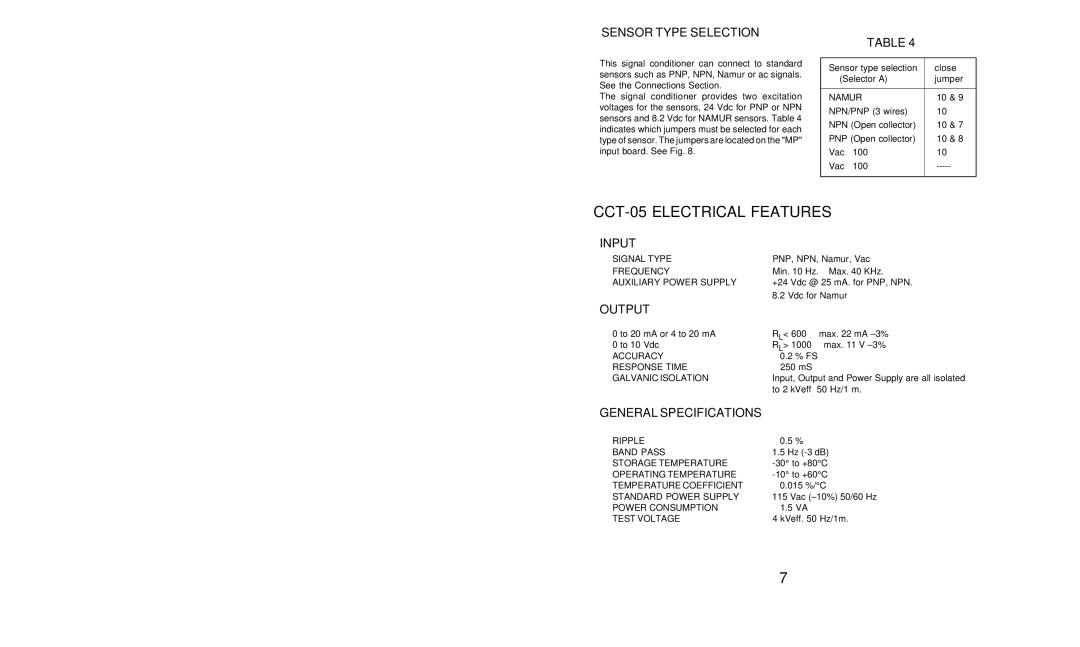
FIG.7
| 1 |
|
P1 | 2 | P2 |
|
|
P1 : Output zero adjustment.
P2 : Gain amplifier adjustment.
B
A
C
Solder pads on solder side
OFFSET ADJUST
Solder pad 1 if closed : Adjust the low range level of the output (Offset positive coarse).
Solder pad 2 if closed : Adjust the low range level of the output (Offset negative coarse).
Jumper A if closed : Adjust the low range level of the output (Offset negative fine).
AMPLIFIER GAIN |
|
Jumper B if closed | : Gain at maximum level |
Jumper C if closed | : Gain at medium level. |
Jumpers B and C opened | : Gain at minimum level. |
6