WIRING RECOMMENDATIONS
Following these suggestions will increase noise immunity and extend the life of the product.
Cable: Make the connection between the count source and the totalizer with a
Relay Coil Suppression: If a relay contact is used as a count source, suppress the relay coil. This can be accom- plished with an RC network for AC coils or a diode for DC coils.
Mounting: Do not mount he totalizer nearasolenoidorother inductive devices. Supply enough ventilation to keep the totalizer operating within the temperature specifications.
BATTERYSAFETY
The lithium battery that powers your device contains inflam- mable materials such as lithium organic solvent, and other chemical ingredients. Explosion or fire may result if the battery is not handled correctly. To avoid an accident follow these guidelines:
??Do not stack or jumble up batteries
??Do not heat batteries above 95°C
??Do not disassemble batteries
??Do not recharge lithium batteries
??Do not apply pressure to, or deform batteries
??Do not solder to batteries
??Do not dispose of batteries in fire
??Insert battery with correct polarity
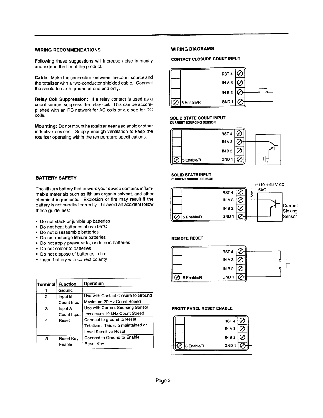
WIRING DIAGRAMS
CONTACT CLOSURE COUNT INPUT
SOLID STATE COUNT INPUT
CURRENT SOURCING SENSOR
6 |
| ;\ |
| RST4 @ | |
| INA | @ |
| INB2 | @ |
\? @ 5 Enable/R | GNDl | @ J |
SOLID STATE INPUT
CURRENT SlNKtNG SENSOR
REMOTE RESET
4 | RST 4 |
| |
| INA |
| INB2 |
@ 5 Enable/R | GND 1 |
‘“I
+6 to +28 V dc
t
Terminal Function
1 Ground
2Input B Count Input
3Input A Count Input
4Reset
5Reset Key
Enable
Operation
Use with Contact Closure to Ground
Maximum 20 Hz Count Speed Use with Current Sourcing Sensor
maximum 10 kHz Count Speed Connect to ground to Reset Totalizer. This is a maintained or Level Sensitive Reset Connect to Ground to Enable Reset Key
FRONT PANEL RESET ENABLE
Page 3