4.0: PSIM Schematic and Pin-out (continued)PSIM-AC PSIM-DC PSIM-5V
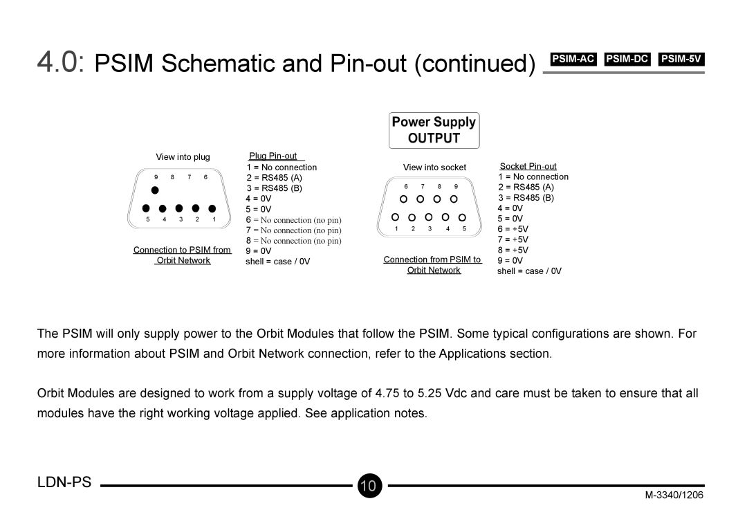
View into plug
9 8 7 6
5 4 3 2 1
Connection to PSIM from Orbit Network
Plug
1 = No connection
2 = RS485 (A)
3 = RS485 (B)
4 = 0V
5 = 0V
6 = No connection (no pin)
7 = No connection (no pin)
8 = No connection (no pin)
9 = 0V
shell = case / 0V
| View into socket | Socket | ||||
|
|
|
|
|
| 1 = No connection |
|
|
|
|
|
| |
6 | 7 | 8 | 9 |
| 2 = RS485 (A) | |
|
|
|
|
|
| 3 = RS485 (B) |
|
|
|
|
|
| 4 = 0V |
|
|
|
|
|
| 5 = 0V |
1 | 2 3 | 4 | 5 | 6 = +5V | ||
|
|
|
|
|
| 7 = +5V |
Connection from PSIM to | 8 = +5V | |||||
9 = 0V | ||||||
| Orbit Network | shell = case / 0V | ||||
The PSIM will only supply power to the Orbit Modules that follow the PSIM. Some typical configurations are shown. For more information about PSIM and Orbit Network connection, refer to the Applications section.
Orbit Modules are designed to work from a supply voltage of 4.75 to 5.25 Vdc and care must be taken to ensure that all modules have the right working voltage applied. See application notes.
|
|
|
|
| 10 |
| |
| |||
|
|
| |
|
|
|