LVR300 Series Quick Reference – Programming Steps
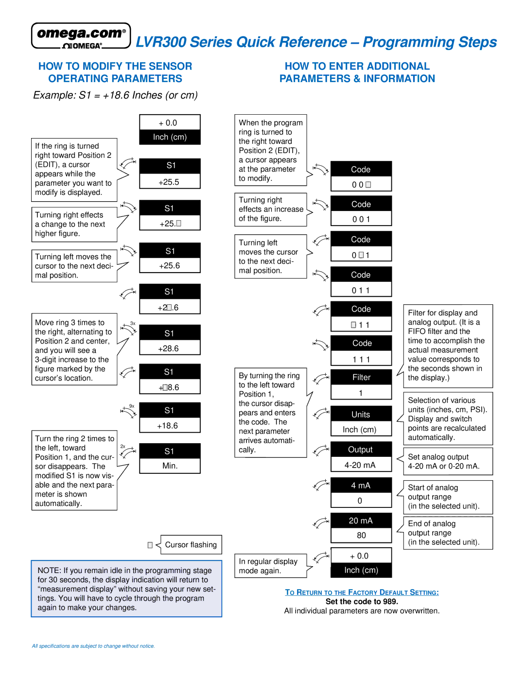
HOW TO MODIFY THE SENSOR
OPERATING PARAMETERS
Example: S1 = +18.6 Inches (or cm)
HOW TO ENTER ADDITIONAL PARAMETERS & INFORMATION
|
| + 0.0 |
| |||||
|
|
|
|
|
|
|
|
|
If the ring is turned |
| Inch (cm) | ||||||
|
|
|
|
|
|
|
| |
|
|
|
|
|
|
|
| |
right toward Position 2 |
|
|
|
|
|
|
|
|
(EDIT), a cursor |
|
| S1 | |||||
appears while the |
|
|
|
|
|
|
|
|
| +25.5 |
| ||||||
parameter you want to |
|
| ||||||
modify is displayed. |
|
|
|
|
|
|
|
|
|
|
|
|
|
|
|
|
|
Turning right effects |
|
| S1 | |||||
| +25. |
|
| |||||
a change to the next |
|
|
| |||||
|
|
| ||||||
|
|
| ||||||
higher figure. |
|
|
|
|
|
|
|
|
|
|
|
|
|
|
|
| |
|
|
|
|
|
|
|
|
|
Turning left moves the |
|
| S1 | |||||
| +25.6 |
| ||||||
cursor to the next deci- |
|
| ||||||
mal position. |
|
|
|
|
|
|
|
|
|
|
|
|
|
|
|
| |
|
|
|
|
|
|
|
|
|
|
|
| S1 | |||||
|
|
|
|
|
|
|
|
|
|
| +2 |
|
| .6 |
| ||
|
| 1 |
| |||||
Move ring 3 times to |
|
|
|
|
|
|
|
|
3x |
|
|
|
|
|
|
| |
the right, alternating to |
|
| S1 | |||||
Position 2 and center, |
| +28.6 |
| |||||
and you will see a |
|
| ||||||
|
|
|
|
|
|
|
| |
figure marked by the |
|
| S1 | |||||
cursor’s location. |
|
| ||||||
|
|
|
|
|
|
|
| |
| + |
|
| 8.6 |
| |||
|
|
|
| |||||
|
| 1 |
| |||||
| 9x |
|
|
|
|
|
|
|
|
| S1 | ||||||
|
|
| ||||||
|
|
|
|
|
|
|
|
|
|
| +18.6 |
| |||||
Turn the ring 2 times to |
|
|
|
|
|
|
|
|
|
|
|
|
|
|
|
| |
the left, toward | 2x |
| ||||||
|
| S1 | ||||||
Position 1, and the cur- |
|
| ||||||
| Min. | |||||||
sor disappears. The |
| |||||||
modified S1 is now vis- |
|
|
|
|
|
|
|
|
|
|
|
|
|
|
|
| |
able and the next para- |
|
|
|
|
|
|
|
|
meter is shown |
|
|
|
|
|
|
|
|
automatically. |
|
|
|
|
|
|
|
|
Cursor flashing
NOTE: If you remain idle in the programming stage for 30 seconds, the display indication will return to “measurement display” without saving your new set-
When the program ring is turned to the right toward Position 2 (EDIT), a cursor appears at the parameter to modify.
Turning right effects an increase of the figure.
Turning left moves the cursor to the next deci- mal position.
By turning the ring to the left toward Position 1,
the cursor disap- pears and enters the code. The next parameter arrives automati- cally.
In regular display mode again.
Code
0 0 0
Code
0 0 1
Code
0 0![]()
![]() 1
1
Code
0 1 1
Code
0 1 1
Code
1 1 1
Filter
1
Units
Inch (cm)
Output
4mA 0
20mA 80
+0.0
Inch (cm)
Filter for display and analog output. (It is a FIFO filter and the time to accomplish the actual measurement value corresponds to the seconds shown in the display.)
Selection of various units (inches, cm, PSI). Display and switch points are recalculated automatically.
Set analog output
Start of analog output range
(in the selected unit).
End of analog output range
(in the selected unit).
tings. You will have to cycle through the program again to make your changes.
TO RETURN TO THE FACTORY DEFAULT SETTING:
Set the code to 989.
All individual parameters are now overwritten.
All specifications are subject to change without notice.