Application Notes: |
| |
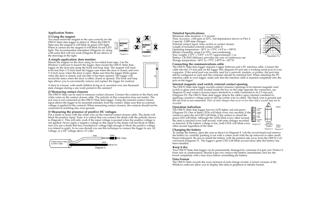
1) Using the magnet |
| |
You must orient the magnet to the case correctly for the |
| |
| ||
State sees the magnet it will blink its green LED light. |
| |
When it cannot see the magnet it will blink its red LED |
| |
light. The recommended orientation (Diagram A), along |
| |
with some that will not work (Diagram B) are shown in | Diagram A | |
the drawings at the right. | ||
Diagram B |
A simple application: door monitor
Mount the magnet on the door using its
A door in a house, with small children living in it, recorded over one thousand state changes during a one week period in the summer!
2) Measuring contact closures
The
Detailed Specifications:
Minimum state duration: 1/2 second
Time Accuracy: ±100 ppm at 20°C, full dependence shown in Plot A
Capacity: 2,000 state changes
External contact input: relay switch or contact closure
Length of included external contact cable: 6'
Operating temperature:
Relative humidity range 0 to 95%,
Size/weight: 2.375" x 1.875" x 0.75"/approximately 1 oz.
Battery:
Storage temperature:
Connecting the communications cable
The
Internal magnetic reed switch, external contact opening
The
connected to anything else, even ground.
3) Measuring the presence of positive DC voltages
Put a diode in series with the white wire on the external contact closure cable. The diode will block the positive input. Note: it is critical that you connect the diode with the polarity shown in Diagram C. This will only work if the input voltage is ground when the positive voltage is not applied. Never apply a negative voltage to this input as the diode will not block it! Make sure you use a diode that has a breakdown voltage high enough to block the positive voltage you intend to apply. In no case should you use this technique to connect the logger to any AC
Operation indication
The
Battery
3.5mm jack
green
LED
red
LED
2.5mm jack
Magnetic
Diagram D
location Holder
voltage, or a DC voltage above 15 volts.
|
|
|
|
|
|
|
|
|
white |
|
| diode |
|
|
|
| |
voltage |
| |||||||
|
|
|
|
|
|
| ||
|
|
|
|
|
|
| ||
contact closure cable |
|
|
|
|
|
|
|
|
black |
| |||||||
to |
| |||||||
|
| ground |
|
| ||||
|
|
|
|
| ||||
Diagram C
Changing the battery | Diagram E | Diagram F |
|
|
To change the battery, open the case as shown in Diagram E. Lift the circuit board and remove the battery by carefully pushing it out with a cotton swab with the tip removed or other small, blunt instrument. Be sure to install the battery with the printed side away from the
Keep it dry
Your
Data Format
The