Programming
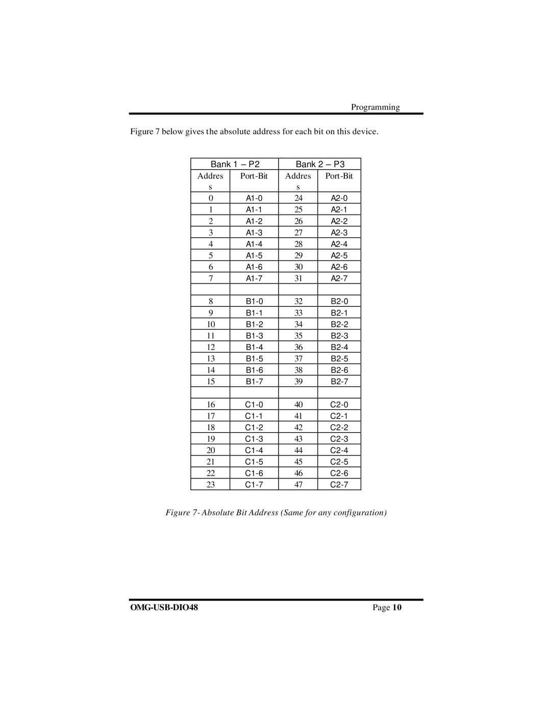
Figure 7 below gives the absolute address for each bit on this device.
Bank 1 – P2 | Bank 2 – P3 | ||
Addres | Addres | ||
s |
| s |
|
0 | 24 | ||
1 | 25 | ||
2 | 26 | ||
3 | 27 | ||
4 | 28 | ||
5 | 29 | ||
6 | 30 | ||
7 | 31 | ||
|
|
|
|
8 | 32 | ||
9 | 33 | ||
10 | 34 | ||
11 | 35 | ||
12 | 36 | ||
13 | 37 | ||
14 | 38 | ||
15 | 39 | ||
|
|
|
|
16 | 40 | ||
17 | 41 | ||
18 | 42 | ||
19 | 43 | ||
20 | 44 | ||
21 | 45 | ||
22 | 46 | ||
23 | 47 | ||
Figure 7- Absolute Bit Address (Same for any configuration)
Page 10 |
