For accurate setpoint calibration, mount the switch on a calibration stand, a pump or catalog Omega DWT 1305 deadweight gauge tester. A suitable reference standard such as a Test Gauge is necessary to observe convenient changes in pressure.
A typical calibration procedure would be as follows:
Note – As indicated above, adjustment of set- point is made by use of 7⁄8˝ nut. Precision switch element mounting screws and bracket adjusting screw are factory sealed and should not be tampered with.
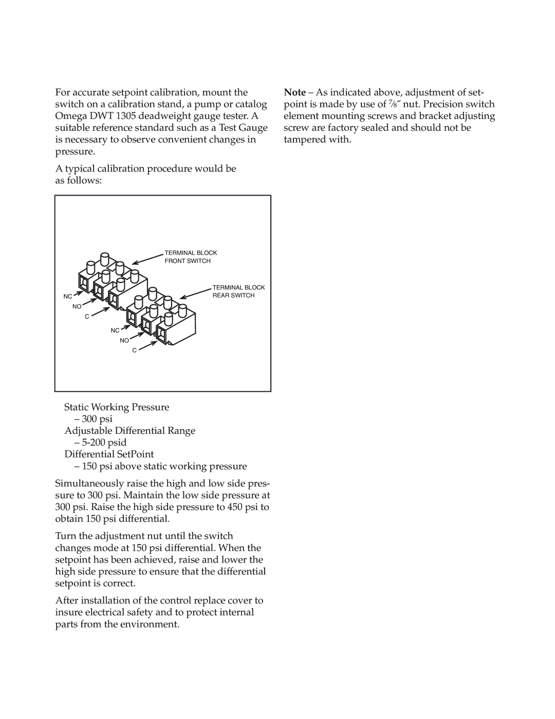
TERMINAL BLOCK
FRONT SWITCH
TERMINAL BLOCK
NC | REAR SWITCH |
NO
C
NC
NO
C
Static Working Pressure
– 300 psi
Adjustable Differential Range
–
–150 psi above static working pressure
Simultaneously raise the high and low side pres- sure to 300 psi. Maintain the low side pressure at 300 psi. Raise the high side pressure to 450 psi to obtain 150 psi differential.
Turn the adjustment nut until the switch changes mode at 150 psi differential. When the setpoint has been achieved, raise and lower the high side pressure to ensure that the differential setpoint is correct.
After installation of the control replace cover to insure electrical safety and to protect internal parts from the environment.