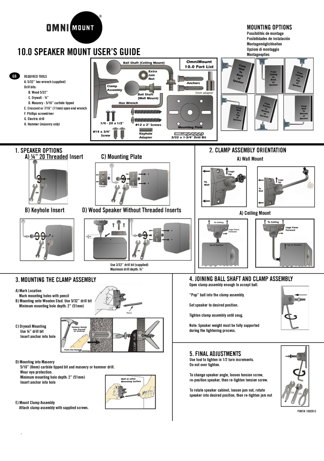
10.0 WALL/CEILING B specifications
The Omnimount 10.0 WALL/CEILING B is a versatile mounting solution designed to provide optimal support for various multimedia equipment, including televisions and projectors. This innovative mounting system is tailored for both wall and ceiling installation, making it an ideal choice for diverse environments such as homes, offices, schools, and commercial spaces.One of the standout features of the Omnimount 10.0 is its robust construction. Built with high-quality materials, this mount ensures durability and longevity, supporting heavy loads without compromising safety. The mount's secure locking mechanism provides peace of mind that your device is safely anchored, while the engineered design reduces the risk of wear and tear over time.
The Omnimount 10.0 offers a high degree of flexibility in terms of installation and adjustment. It features multiple mounting positions, allowing users to easily customize the height and angle of their equipment for the best viewing experience. This is particularly beneficial in settings where viewers may be positioned at varying distances or angles from the screen.
Technology integration is another key aspect of the Omnimount 10.0. The mount is designed to accommodate various cable management systems, effectively keeping cords organized and out of sight. This not only enhances the aesthetic appeal of your setup but also contributes to a clutter-free environment, improving safety and ease of use.
Installation of the Omnimount 10.0 is a straightforward process thanks to its user-friendly design. The package includes comprehensive instructions and all necessary hardware, simplifying the setup for users of all skill levels. Additionally, the mount is engineered to be compatible with a wide range of devices, ensuring that whether you have a modern flat-screen TV or an older projection system, the Omnimount 10.0 will meet your needs.
Moving beyond functionality, the Omnimount 10.0 WALL/CEILING B also embodies a sleek and modern aesthetic that complements any room decor. Its minimalistic design ensures that it blends seamlessly with other elements in your space while providing a sturdy and reliable mount for your technology.
In summary, the Omnimount 10.0 WALL/CEILING B is an exceptional choice for anyone looking to optimize their multimedia setup. With its robust construction, flexible mounting options, integrated technology solutions, and user-friendly design, it stands as a reliable mounting solution that enhances both functionality and style in any environment.

