miConverter™ | 10/100 Plus | |
| Media Converter | | |
| User Manual | | |
| | | | | | |
miConverter 10/100 Plus Models | | |
Fiber Mode Type / | | Connector Types | | Tx | Rx |
Dual Fiber [DF] or | Distance | | | | | Lambda | Lambda |
Single-Fiber [SF] | | ST | SC | | [nm] | [nm] |
MM / DF | 5km | 1120-0-x | 1122-0-x | | 1310 | 1310 |
SM / DF | 30km | 1121-1-x | 1123-1-x | | 1310 | 1310 |
SM / DF | 60km | 1121-2-x | 1123-2-x | | 1310 | 1310 |
SM / DF | 120km | | - | 1123-3-x | | 1550 | 1550 |
SM / SF | 20km | | - | 1130-1-x | | 1310 | 1550 |
SM / SF | 40km | | - | 1130-2-x | | 1310 | 1550 |
SM / SF | 20km | | - | 1131-1-x | | 1550 | 1310 |
SM / SF | 40km | | - | 1131-2-x | | 1550 | 1310 |
When choosing power options, replace (-x) in the model number with the suffix number that corresponds to the power supply of choice below. Example: 1103-3-6 stands for
1103-3-x with USB Power Adapter
-1 US Power Supply - 120Volt / 60Hz
-2 Universal Power Supply (requires AC power cord) - 100-240Volt / 50-60Hz
-3 Euro Power Supply - 100-240Volt / 50-60Hz -4 UK Power Supply - 100-240Volt / 50-60Hz
-5 Australia Power Supply - 100-240Volt / 50-60Hz -6 USB Power Adapter Cable
-8 US/JPN Power Supply - 100-240Volt / 50-60Hz
For power supplies -3, -4, -5 and -8, country/region specific clips are used to provide the necessary power connection.
Page 1
Accessories
| Wall Mounting Hardware Kit | 4381 |
| | |
| USB Power Adapter Cable | 9130-2 |
| US Domestic AC Power Adapter | 9113-PS |
| | |
| Universal AC Power Adapter | 9115-PS |
| (requires AC power cord) |
| |
| Europe AC Power Adapter | 9116-PS-3 |
| United Kingdom AC Power Adapter | 9116-PS-4 |
| Australia AC Power Adapter | 9116-PS-5 |
| Japanese AC Power Adapter | 9116-PS-8 |
| European Connector Clip* | 9116-3 |
| UK Connector Clip* | 9116-4 |
| Australian Connector Clip* | 9116-5 |
| Japanese Connector Clip* | 9116-8 |
*All spare Connector Clips are interchangeable with AC Power Adapters 9116-PS-3, 9116-PS-4, 9116-PS-5 and 9116-PS-8
DESCRIPTION
The miConverter™ 10/100 Plus is a 10/100BASE-T copper to 100BASE-FX fiber media converter. The UTP copper port can automatically detect the speed, duplex mode and crossover mode of the connected device, or it can be manually configured via DIP-switches.
The 100BASE-FX fiber port operates in Full-Duplex mode and supports single-mode or multimode fiber with ST or SC fiber connectors. Single-mode models feature Bi-Directional fiber and support distances of up to 40km. The various fiber models options are described in the table on the first page.
Several Link Modes (fault-detection capabilities) are
Page 2
available with the 10/100 Plus, including Link Segment (Normal Mode), Link Propagate (Link Loss Carry Forward), Remote Fault Detection and Symmetrical Fault Detection. The link mode assist in the identification and isolation of link failures.
WARNING!
Before inserting the Power Adapter, verify that the power on the unit is appropriate for your AC line voltage source.
POWER ADAPTER NOTICE
This product should only be used with Omnitron supplied Power Supply model numbers 9113-PS, 9115-PS, 9130-2, 9116-PS-3, 9116-PS-4, 9116-PS-5 or 9116-PS-8.
In order to guarantee performance when powering the miConverter 10/100 Plus with the USB Power Adapter cable (P/N 9130-2), the cable must be connected to a Full-Powered USB Type-A port (5V, 500mA).
NOTE: Not all USB Type-A ports are Full-Powered USB ports. The Full-Powered USB Type-A ports are usually the USB ports found on computer cases or on self-powered (powered by an AC adapter) USB hubs.
INSTALLATION PROCEDURE
1.Configure the miConverter 10/100 Plus with the appropriate DIP-switch settings. The factory default configuration for the UTP copper port is “AN” Auto-
Page 3
negotiation and the Link Mode is “LS” Link Segment.
2.Connect the UTP port to a 10BASE-T or 100BASE-TX Ethernet device using a Category 5 cable (or better).
3.Connect the fiber optic port to a 100BASE-FX Fast Ethernet device via the fiber cable of the appropriate mode and type. When connecting dual fiber models, the miConverter 10/100 Plus transmitter (Tx) must attach to the receiver side of its link partner; the receiver (Rx) must attach to the transmitter. When connecting single-fiber (SF) models, the Tx wavelength on one end has to match the Rx wavelength on the other. Based on this guideline, the SF media converter models must be used in pairs, such as the 1130-2-x matched with the 1131-2-x.
4.Mount the miConverter 10/100 Plus using the included Velcro® strips or optional wall-mounting bracket kit (P/N 1091-0).
5.Connect the appropriate power source.
DIP-SWITCH SETTINGS
Link Mode | UTP Mode |
| | | | | | | | | | | |
| | | | | | | | | | | |
LS (default) | | | | | | | | | AN Auto (default) |
LP | | | | | | | | | MAN 10Mbps HD |
| | | | | | | | | | MAN 100Mbps HD |
| | | | | | | | | |
| | | | | | | | | | MAN 100Mbps FD |
Figure 1: DIP-switch Configurations
Page 4
UTP Mode Selection
The UTP port is configured using the DIP-switches as shown in Figure 1. There are four modes of operation based on the position of the DIP-switches.
The factory default configuration is “AN” Auto- negotiation. In the “AN” mode, the port will advertise 100Mbps Full-Duplex, 100Mbps Half-Duplex, 10Mbps Full-Duplex and 10Mbps Half-Duplex.
The UTP port can be configured for Manual negotiation by setting the appropriate DIP-switches. The port can be configured for 100Mbps Full-Duplex, 100Mbps Half-Duplex and 10Mbps Half-Duplex.
Link Mode Selection
The miConverter 10/100 Plus can be configured for several different Link Modes. The DIP-switch illustration in Figure 1 indicates how to configure the
Link Propagate (LP)
“LP” generates (transmits) a link signal only when a link signal is detected. Utilizing this configuration, a loss of a receive link signal will continue to ‘propagate’ through to the next port in the network. In Figure 2(C), a loss of a receive link on the fiber optic port causes the UTP port to drop its link due to the propagated fiber optic link state. This setting allows the loss of a link to be detected by SNMP or other managed network devices to which the miConverter 10/100 Plus is connected.
NOTE: Only the first loss of a receive link detected by the miConverter 10/100 Plus turns off the other port’s transmit link. An additional loss of a receive link on the other port has no affect on the miConverter 10/100 Plus. The miConverter 10/100 Plus returns to normal
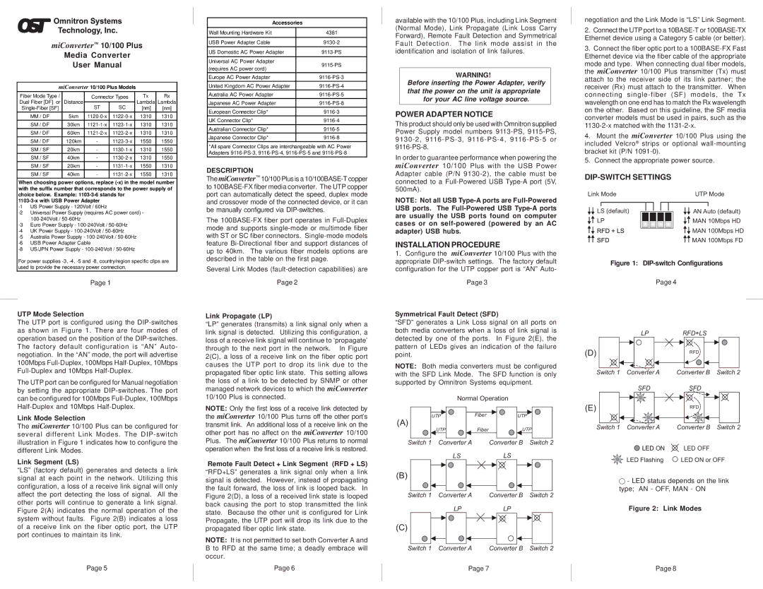
Symmetrical Fault Detect (SFD)
“SFD” generates a Link Loss signal on all ports on both media converters when a loss of link signal is detected by one of the ports. In Figure 2(E), the pattern of LEDs gives an indication of the failure point.
NOTE: Both media converters must be configured with the SFD Link Mode. The SFD function is only supported by Omnitron Systems equipment.
Normal Operation
UTP | Fiber | UTP |
(A) | | |
UTP | Fiber | UTP |
Switch 1 Converter A | | Converter B Switch 2 |
LP
(D)
Switch 1 Converter A
SFD
(E)
Switch 1 Converter A
RFD+LS
RFD
Converter B Switch 2
Converter B Switch 2
different Link Modes.
Link Segment (LS)
“LS” (factory default) generates and detects a link signal at each point in the network. Utilizing this configuration, a loss of a receive link signal will only affect the port detecting the loss of signal. All the other ports will continue to generate a link signal. Figure 2(A) indicates the normal operation of the system without faults. Figure 2(B) indicates a loss of a receive link on the fiber optic port, the UTP port continues to maintain its link.
Page 5
operation when the first loss of a receive link is restored.
Remote Fault Detect + Link Segment (RFD + LS) “RFD+LS” generates a link signal only when a link signal is detected. However, instead of propagating the fault forward, the loss of link is looped back. In Figure 2(D), a loss of a received link state is looped back causing the port to stop transmitted the link state. Because the other unit is configured for Link Propagate, the UTP port will drop its link due to the propagated fiber optic link state.
NOTE: It is not permitted to set both Converter A and B to RFD at the same time; a deadly embrace will occur.
Page 6
| LS | LS | |
(B) | | | |
Switch 1 | Converter A | Converter B | Switch 2 |
| LP | LP | |
(C) | | | |
Switch 1 | Converter A | Converter B | Switch 2 |
Page 7
 LED ON
  LED OFF
LED Flashing | LED ON or OFF |
 - LED status depends on the link type; AN - OFF, MAN - ON
Figure 2: Link Modes
Page 8