iConverter™ Redundant Fast Ethernet Module
User Manual
Port A
Port C
Port B
iConverter Tx/2Fx Dual Fiber Modules
Fiber | Distance |
| Connector Type |
| ||
|
|
|
| |||
Type | ST | SC |
| LC | ||
| ||||||
|
| |||||
|
|
|
|
|
| |
MM | 5km | - | ||||
|
|
|
|
|
| |
SM | 30km | |||||
|
|
|
|
|
| |
SM | 60km | - | ||||
|
|
|
|
|
| |
SM | 120km | - | - | - | ||
|
|
|
|
|
| |
iConverter Tx/2Fx SF |
| |||||
|
|
|
|
|
| |
Fiber / |
| Tx: 1310 nm, | Tx: 1550 nm, | |||
Connector | Distance | |||||
Rx: 1550 nm | Rx: 1310 nm | |||||
Type |
| |||||
|
|
|
|
| ||
SM / SC | 20 km | |||||
|
|
|
|
|
| |
SM / SC | 40 km | |||||
|
|
|
|
|
| |
| iConverter Tx/2Tx |
|
| |||
|
|
|
|
|
| |
Distance |
|
|
| |||
|
|
|
|
|
| |
100m |
|
|
|
|
| |
|
|
|
|
|
| |
For wide temperature
When using
OVERVIEW:
The iConverter Redundant Fast Ethernet manageable media converters are members of the modular iConverter product family. The following models are described:
Tx/2Fx
Tx/2Tx 100BASE-TX UTP to dual 100BASE-FX UTP
The iConverter Redundant Fast Ethernet modules are intended for use in networks that require fiber or copper link redundancy. During normal operations Port A is the active primary and Port B is the backup secondary. When loss of link on Port A is detected, the module automatically switches to transmitting on Port B. With a switch over time of less than 100 microseconds, these modules provide the rapid response time required for ultra critical applications. Note: After the link is switched, there will be a 5 second delay before that link can been reestablished.
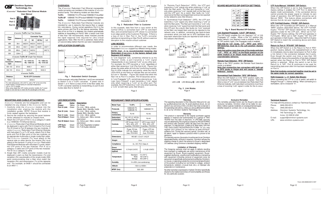
APPLICATION EXAMPLES:
Fig. 1 Redundant Switch Example
In this example, redundant Switches 1 and 2 are connected to Switch 3 via a Tx/2Fx converter. If power fails in Switch 1, or if there is a loss of link in the fiber cable, the Tx/2Fx converter switches to transmitting on port B and routes data flow to Switch 2.
Page 2
Fig. 2 Redundant Fiber to Customer
In this example, data flow from a core switch at the Central Office is converted from UTP to redundant fiber, and converted back to UTP, where it is connected to an edge switch at the Customer Premises. If there is a loss of link in fiber Port A, the Tx/2Fx converter switches to transmitting on fiber Port B, without a service disruption to the
LINK MODES:
In order to accommodate different user needs, the Redundant iConverters support four different linking modes.
NOTE that it is recommended keeping the Redundant iConverters in the factory default Link Segment (LS) setting.
In “Link Segment” (LS), sometimes referred to as the “Normal” mode, a port transmits a “Link” signal independently of any received “Link” at any other port. For example, the UTP transmits a “Link” regardless of either fiber receiving a “Link” [Fig 3(a) & (b)]. Figure 3(a) shows the state when all links are functioning correctly. Port A LEDs indicate link and activity, while the Port B LEDs blink at one Hertz to indicate they are not active, but are in “Standby”. Figure 3(b) shows that when the fiber link to Port A is broken, Port B becomes active.
In “Link Propagate” (LP), sometimes referred to as “Link Loss Carry Forward”, a port transmits a “Link” signal only when receiving a “Link” at its other port. For example, the UTP transmits a “Link” only when receiving a “Link” at both fiber ports (Not Shown).
Page 3
In “Remote Fault Detection” (RFD), the UTP port transmits a “Link” signal only when receiving a “Link” at both the fiber ports. The fiber port transmits a “Link” only when receiving “Link” signals both at the fiber port and the UTP port. As a result, fiber faults (no “Link” received at the fiber) are
In “Symmetrical Fault Detection” (SFD), the UTP port transmits a “Link” signal only when receiving a “Link” at both the fiber ports. The fiber port transmits a “Link” only when receiving “Link” signal from both the fiber ports and the UTP port. As a result, fiber faults (no “Link” received at the fiber) are looped back and can be reported to the network core. In addition, connecting two
Fig. 3 Link Modes
Page 4
BOARD MOUNTED DIP-SWITCH SETTINGS:
Fig. 4 Board Mounted DIP-Switches
Link Segment/Propagate “LS/LP” DIP-Switch:
This
Note that for “LS” mode, “LP”, “RFD” and “SFD”,
Note that setting more than one of the mode switches (“LP”, “RFD” or “SFD”) to the Right position on the same module is an illegal mode that will result in unpredictable behavior.
Remote Fault Detection “RFD”
When in the “RFD” position, the Remote Fault Detection mode is enabled.
Note that connecting two converters with both set to RFD mode is illegal and will cause a “deadly embrace” lockup.
Symmetrical Fault Detection “SFD” DIP-Switch:
When this
Page 5
UTP Auto/Manual “AN/MAN” DIP-Switch:
When this
UTP Full/Half-Duplex “FD/HD” DIP-Switch:
When the UTP Auto/Manual
Return to Port A “RTA/NR” DIP-Switch:
When this
Note that modules connected together must be set to the same mode for correct operation.
RJ45 Crossover “= / X” Switch (Not Shown):
When connecting the UTP to a hub or switch, set switch to
Page 6
MOUNTING AND CABLE ATTACHMENT:
iConverter modules are
1.Carefully slide the iConverter module into the installation slot, aligning the module with the installation guides. NOTE: Ensure that module is firmly seated against the backplane.
2.Secure the module by securing the panel fastener screw (attached to module) to chassis front.
3.Attach the UTP port of Port C via a category 5 cable to a
4.iConverter Redundant Fast Ethernet Modules should be deployed in pairs with Port A linked to Port A and Port B linked to Port B between the two modules. If using iConverter Redundant Fast Ethernet Modules with redundant Fx or Fx SF ports, attach Port A fiber ports and Port B fiber ports of the two modules via an appropriate multimode or
5.Single fiber (SF) media converter models must be deployed in pairs so that the transmission (Tx) and reception (Rx) wavelengths of the
LED INDICATORS:
LED | Color | Description |
Power: | Yellow | |
Port A Link: | Green | |
Port B Link: |
| Steady |
Green | ||
Port C Link: |
| Steady |
Green | ||
Port A Select: Green | ||
Port B Select: Green | side broken | |
UTP Auto: |
| side broken |
Green | ||
UTP FDx: | Green | |
REDUNDANT FIBER SPECIFICATIONS:
Model Type | Tx/2Fx |
| Tx/2Tx |
|
|
|
|
Protocols |
| ||
| |||
|
|
| |
Primary |
| ||
Connectors |
| ||
|
|
| |
Redundant | SC, ST, LC, |
| |
Connectors |
| ||
|
| ||
Controls | UTP |
| UTP |
RFD, SFD, UTP |
| RFD, SFD, UTP | |
| Auto/Man, FDX/HDX |
| Auto/Man, FDX/HDX |
LED Displays | Power, FO link, |
| Power, UTP link, |
UTP link, Select, |
| UTP link, Select, | |
| Auto, FDX/HDX |
| Auto, FDX/HDX |
|
|
| |
Dimensions | W:0.85" x D:4.5" x H:2.8" | ||
|
|
| |
Weight | 8 oz. | ||
|
|
| |
Compliance | UL, CE, FCC Class A | ||
|
|
|
|
Power |
|
|
|
Requirement | 0.7A @ 3.3VDC |
| 1.1A @ 3.3VDC |
(typical) |
|
|
|
|
|
|
|
Temperature | Standard: | 0 to 50º C | |
Wide: | |||
| Storage: | ||
|
|
| |
Humidity | 5 to 95% | ||
|
|
| |
Altitude | |||
|
|
| |
MTBF (hrs) | 520, 000 | ||
|
|
|
|
Warning
The operating description in this Instruction Manual is for use by qualified personnel only. To avoid electrical shock, do not perform any servicing of this unit other than that contained in the operating instructions, unless you are qualified and certified to do so by Omnitron Systems Technology, Inc.
Warranty
This product is warranted to the original purchaser against defects in material and workmanship for a period of TWO YEARS from the date of shipment. A LIFETIME warranty may be obtained by the original purchaser by REGISTERING this product with Omnitron within 90 days from the date of shipment. TO REGISTER, COMPLETE AND MAIL OR FAX THE ENCLOSED REGISTRATION FORM. Or you may register your product on the Internet at www.omnitron- systems.com. During the warranty period, Omnitron will, at its option, repair or replace a product which is proven to be defective.
For warranty service, the product must be sent to an Omnitron designated facility, at Buyer’s expense. Omnitron will pay the shipping charge to return the product to Buyer’s designated US address using Omnitron’s standard shipping method.
Limitation of Warranty
The foregoing warranty shall not apply to defects resulting from improper or inadequate use and/or maintenance of the equipment by Buyer,
No other warranty is expressed or implied. Omnitron specifically disclaims the implied warranties of merchantability and fitness for any particular purpose.
Exclusive Remedies
The remedies provided herein are the Buyer’s sole and exclusive remedies. Omnitron shall not be liable for any direct, indirect, special, incidental, or consequential damages, whether based on contract, tort, or any legal theory.
Technical Support:
For help with this product, contact our Technical Support:
Phone: | (949) |
Fax: | (949) |
Address: Omnitron Systems Technology, Inc.
140 Technology Dr., #500 Irvine, CA 92618 USA
URL:
Form:
Page 7 | Page 8 | Page 9 | Page 10 | Page 11 | Page 12 |