DIP-SWITCH SETTINGS
Front Panel
Fig. 3 Front Panel DIP-Switches
Link Segment/Link Propagate “LS/LP” DIP-Switch
This
Remote Fault Detection “RFD” DIP-Switch
To enable Remote Fault Detection mode, set the “RFD”
To enable RFD + LS mode, also set the LS/LP DIP- Switch to the “LS” position. Toenable RFD + LP mode, set the LS/LP
The RFD
NOTE: Connecting two converters with both set to RFD mode is not supported and will cause a “deadly embrace” lockup.
Symmetrical Fault Detection “SFD” DIP-Switch
To enable Symmetrical Fault Detection mode, set the “SFD”
Any other
Page 9
NOTE: Converters in SFD mode must be deployed in pairs.
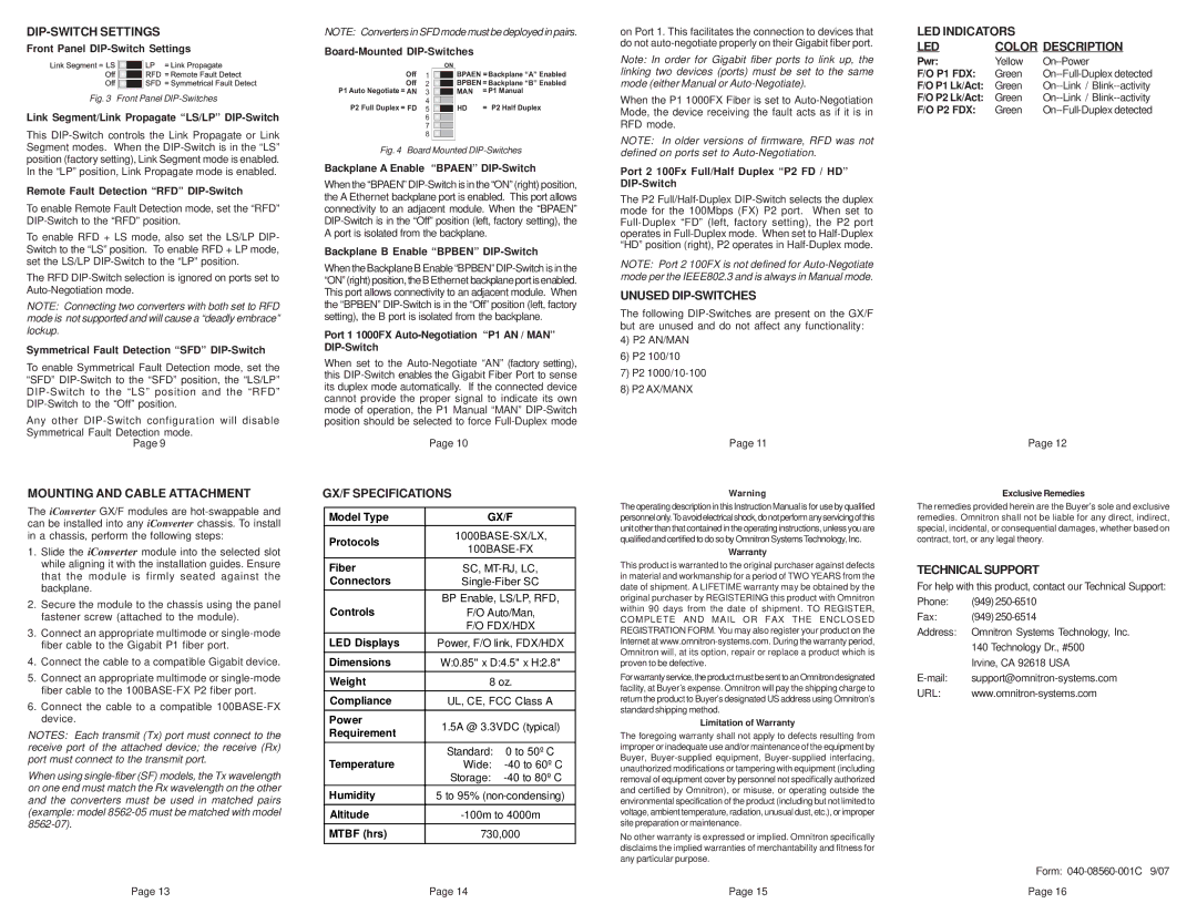
Board-Mounted DIP-Switches
|
|
| ON |
| |
Off | 1 |
|
| BPAEN = Backplane “A” Enabled | |
Off | 2 |
|
| BPBEN = Backplane “B” Enabled | |
|
| ||||
P1 Auto Negotiate = AN | 3 |
|
| MAN | = P1 Manual |
|
| ||||
P2 Full Duplex = FD | 4 |
|
| HD | = P2 Half Duplex |
|
| ||||
5 |
|
| |||
|
| ||||
| 6 |
|
|
|
|
| 7 |
|
|
|
|
|
|
|
|
| |
| 8 |
|
|
|
|
|
|
|
|
| |
|
|
|
|
|
|
|
|
|
|
|
|
Fig. 4 Board Mounted DIP-Switches
Backplane A Enable “BPAEN” DIP-Switch
When the “BPAEN”
Backplane B Enable “BPBEN” DIP-Switch
When the Backplane B Enable “BPBEN”
Port 1 1000FX Auto-Negotiation “P1 AN / MAN” DIP-Switch
When set to the
Page 10
on Port 1. This facilitates the connection to devices that do not
Note: In order for Gigabit fiber ports to link up, the linking two devices (ports) must be set to the same mode (either Manual or
When the P1 1000FX Fiber is set to
NOTE: In older versions of firmware, RFD was not defined on ports set to
Port 2 100Fx Full/Half Duplex “P2 FD / HD” DIP-Switch
The P2
NOTE: Port 2 100FX is not defined for
UNUSED DIP-SWITCHES
The following
4)P2 AN/MAN
6)P2 100/10
7)P2
8)P2 AX/MANX
Page 11
LED INDICATORS |
| |
LED | COLOR DESCRIPTION | |
Pwr: | Yellow | |
F/O P1 FDX: | Green | |
F/O P1 Lk/Act: | Green | |
F/O P2 Lk/Act: | Green | |
F/O P2 FDX: | Green | |
Page 12
MOUNTING AND CABLE ATTACHMENT
The iConverter GX/F modules are
1.Slide the iConverter module into the selected slot while aligning it with the installation guides. Ensure that the module is firmly seated against the backplane.
2.Secure the module to the chassis using the panel fastener screw (attached to the module).
3.Connect an appropriate multimode or
4.Connect the cable to a compatible Gigabit device.
5.Connect an appropriate multimode or
6.Connect the cable to a compatible
NOTES: Each transmit (Tx) port must connect to the receive port of the attached device; the receive (Rx) port must connect to the transmit port.
When using
Page 13
GX/F SPECIFICATIONS
Model Type | GX/F | ||
|
| ||
Protocols | |||
| |||
|
| ||
Fiber | SC, | ||
Connectors | |||
|
| ||
| BP Enable, LS/LP, RFD, | ||
Controls | F/O Auto/Man, | ||
| F/O FDX/HDX | ||
LED Displays | Power, F/O link, FDX/HDX | ||
|
| ||
Dimensions | W:0.85" x D:4.5" x H:2.8" | ||
|
| ||
Weight | 8 oz. | ||
|
| ||
Compliance | UL, CE, FCC Class A | ||
|
|
| |
Power | 1.5A @ 3.3VDC (typical) | ||
Requirement | |||
|
| ||
|
|
| |
Temperature | Standard: | 0 to 50º C | |
Wide: | |||
| Storage: | ||
Humidity | 5 to 95% | ||
|
| ||
Altitude | |||
|
| ||
MTBF (hrs) | 730,000 | ||
|
|
| |
Page 14
Warning
The operating description in this Instruction Manual is for use by qualified personnelonly.Toavoidelectricalshock,donotperformanyservicingofthis unit other than that contained in the operating instructions, unless you are qualified and certified to do so by Omnitron Systems Technology, Inc.
Warranty
This product is warranted to the original purchaser against defects in material and workmanship for a period of TWO YEARS from the date of shipment. A LIFETIME warranty may be obtained by the original purchaser by REGISTERING this product with Omnitron within 90 days from the date of shipment. TO REGISTER, COMPLETE AND MAIL OR FAX THE ENCLOSED REGISTRATION FORM. You may also register your product on the Internet at
For warranty service, the product must be sent to an Omnitron designated facility, at Buyer’s expense. Omnitron will pay the shipping charge to return the product to Buyer’s designated US address using Omnitron’s standard shipping method.
Limitation of Warranty
The foregoing warranty shall not apply to defects resulting from improper or inadequate use and/or maintenance of the equipment by Buyer,
No other warranty is expressed or implied. Omnitron specifically disclaims the implied warranties of merchantability and fitness for any particular purpose.
Page 15
Exclusive Remedies
The remedies provided herein are the Buyer’s sole and exclusive remedies. Omnitron shall not be liable for any direct, indirect, special, incidental, or consequential damages, whether based on contract, tort, or any legal theory.
TECHNICAL SUPPORT
For help with this product, contact our Technical Support:
Phone: | (949) |
Fax: | (949) |
Address: | Omnitron Systems Technology, Inc. |
| 140 Technology Dr., #500 |
| Irvine, CA 92618 USA |
URL: |
Form:
Page 16