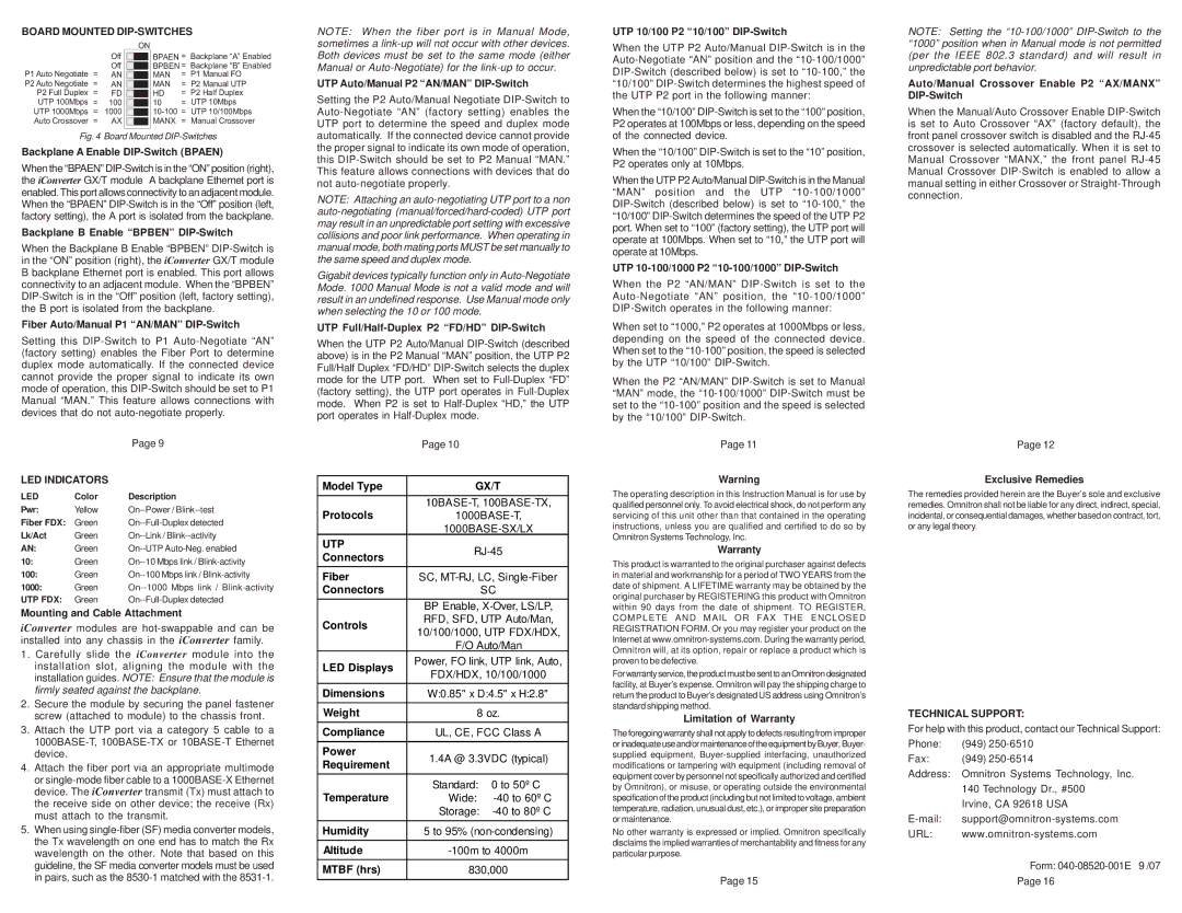
BOARD MOUNTED DIP-SWITCHES
| | ON | | |
| Off | | | BPAEN = | Backplane “A” Enabled |
| Off | | | BPBEN = | Backplane “B” Enabled |
| | |
P1 Auto Negotiate = | AN | | | MAN | = | P1 Manual FO |
| |
P2 Auto Negotiate = | AN | | | MAN | = | P2 Manual UTP |
| |
P2 Full Duplex = | FD | | | HD | = | P2 Half Duplex |
| |
UTP 100Mbps = | 100 | | | 10 | = | UTP 10Mbps |
| |
UTP 1000Mbps = | 1000 | | | 10-100 = | UTP 10/100Mbps |
| |
Auto Crossover = | AX | | | MANX | = | Manual Crossover |
| |
| | | | | | |
Fig. 4 Board Mounted DIP-Switches
Backplane A Enable DIP-Switch (BPAEN)
When the “BPAEN” DIP-Switch is in the “ON” position (right), the iConverter GX/T module A backplane Ethernet port is enabled. This port allows connectivity to an adjacent module. When the “BPAEN” DIP-Switch is in the “Off” position (left, factory setting), the A port is isolated from the backplane.
Backplane B Enable “BPBEN” DIP-Switch
When the Backplane B Enable “BPBEN” DIP-Switch is in the “ON” position (right), the iConverter GX/T module B backplane Ethernet port is enabled. This port allows connectivity to an adjacent module. When the “BPBEN” DIP-Switch is in the “Off” position (left, factory setting), the B port is isolated from the backplane.
Fiber Auto/Manual P1 “AN/MAN” DIP-Switch
Setting this DIP-Switch to P1 Auto-Negotiate “AN” (factory setting) enables the Fiber Port to determine duplex mode automatically. If the connected device cannot provide the proper signal to indicate its own mode of operation, this DIP-Switch should be set to P1 Manual “MAN.” This feature allows connections with devices that do not auto-negotiate properly.
| | Page 9 |
LED INDICATORS | |
LED | Color | Description |
Pwr: | Yellow | On--Power / Blink--test |
Fiber FDX: | Green | On--Full-Duplex detected |
Lk/Act | Green | On--Link / Blink--activity |
AN: | Green | On--UTP Auto-Neg. enabled |
10: | Green | On--10 Mbps link / Blink-activity |
100: | Green | On--100 Mbps link / Blink-activity |
1000: | Green | On--1000 Mbps link / Blink-activity |
UTP FDX: | Green | On--Full-Duplex detected |
Mounting and Cable Attachment
iConverter modules are hot-swappable and can be installed into any chassis in the iConverter family.
1.Carefully slide the iConverter module into the installation slot, aligning the module with the installation guides. NOTE: Ensure that the module is firmly seated against the backplane.
2.Secure the module by securing the panel fastener screw (attached to module) to the chassis front.
3.Attach the UTP port via a category 5 cable to a 1000BASE-T, 100BASE-TX or 10BASE-T Ethernet device.
4.Attach the fiber port via an appropriate multimode or single-mode fiber cable to a 1000BASE-X Ethernet device. The iConverter transmit (Tx) must attach to the receive side on other device; the receive (Rx) must attach to the transmit.
5.When using single-fiber (SF) media converter models, the Tx wavelength on one end has to match the Rx wavelength on the other. Note that based on this guideline, the SF media converter models must be used in pairs, such as the 8530-1 matched with the 8531-1.
NOTE: When the fiber port is in Manual Mode, sometimes a link-up will not occur with other devices. Both devices must be set to the same mode (either Manual or Auto-Negotiate) for the link-up to occur.
UTP Auto/Manual P2 “AN/MAN” DIP-Switch
Setting the P2 Auto/Manual Negotiate DIP-Switch to Auto-Negotiate “AN” (factory setting) enables the UTP port to determine the speed and duplex mode automatically. If the connected device cannot provide the proper signal to indicate its own mode of operation, this DIP-Switch should be set to P2 Manual “MAN.” This feature allows connections with devices that do not auto-negotiate properly.
NOTE: Attaching an auto-negotiating UTP port to a non auto-negotiating (manual/forced/hard-coded) UTP port may result in an unpredictable port setting with excessive collisions and poor link performance. When operating in manual mode, both mating ports MUST be set manually to the same speed and duplex mode.
Gigabit devices typically function only in Auto-Negotiate Mode. 1000 Manual Mode is not a valid mode and will result in an undefined response. Use Manual mode only when selecting the 10 or 100 mode.
UTP Full/Half-Duplex P2 “FD/HD” DIP-Switch
When the UTP P2 Auto/Manual DIP-Switch (described above) is in the P2 Manual “MAN” position, the UTP P2 Full/Half Duplex “FD/HD” DIP-Switch selects the duplex mode for the UTP port. When set to Full-Duplex “FD” (factory setting), the UTP port operates in Full-Duplex mode. When P2 is set to Half-Duplex “HD,” the UTP port operates in Half-Duplex mode.
| | Page 10 | |
| | |
| Model Type | GX/T |
| Protocols | 10BASE-T, 100BASE-TX, |
| 1000BASE-T, |
| | 1000BASE-SX/LX |
| UTP | RJ-45 |
| Connectors |
| | |
| Fiber | SC, MT-RJ, LC, Single-Fiber |
| Connectors | | SC |
| | BP Enable, X-Over, LS/LP, |
| Controls | RFD, SFD, UTP Auto/Man, |
| 10/100/1000, UTP FDX/HDX, |
| |
| | F/O Auto/Man |
| LED Displays | Power, FO link, UTP link, Auto, |
| FDX/HDX, 10/100/1000 |
| |
| Dimensions | W:0.85" x D:4.5" x H:2.8" |
| | |
| Weight | 8 oz. |
| Compliance | UL, CE, FCC Class A |
| Power | 1.4A @ 3.3VDC (typical) |
| Requirement |
| | |
| Temperature | Standard: | 0 to 50º C |
| Wide: | -40 to 60º C |
| | Storage: | -40 to 80º C |
| Humidity | 5 to 95% (non-condensing) |
| Altitude | -100m to 4000m |
| MTBF (hrs) | 830,000 |
| | | |
UTP 10/100 P2 “10/100” DIP-Switch
When the UTP P2 Auto/Manual DIP-Switch is in the Auto-Negotiate “AN” position and the “10-100/1000” DIP-Switch (described below) is set to “10-100,” the “10/100” DIP-Switch determines the highest speed of the UTP P2 port in the following manner:
When the “10/100” DIP-Switch is set to the “100” position, P2 operates at 100Mbps or less, depending on the speed of the connected device.
When the “10/100” DIP-Switch is set to the “10” position, P2 operates only at 10Mbps.
When the UTP P2 Auto/Manual DIP-Switch is in the Manual “MAN” position and the UTP “10-100/1000” DIP-Switch (described below) is set to “10-100,” the “10/100” DIP-Switch determines the speed of the UTP P2 port. When set to “100” (factory setting), the UTP port will operate at 100Mbps. When set to “10,” the UTP port will operate at 10Mbps.
UTP 10-100/1000 P2 “10-100/1000” DIP-Switch
When the P2 “AN/MAN” DIP-Switch is set to the Auto-Negotiate “AN” position, the “10-100/1000” DIP-Switch operates in the following manner:
When set to “1000,” P2 operates at 1000Mbps or less, depending on the speed of the connected device. When set to the “10-100” position, the speed is selected by the UTP “10/100” DIP-Switch.
When the P2 “AN/MAN” DIP-Switch is set to Manual “MAN” mode, the “10-100/1000” DIP-Switch must be set to the “10-100” position and the speed is selected by the “10/100” DIP-Switch.
Page 11
Warning
The operating description in this Instruction Manual is for use by qualified personnel only. To avoid electrical shock, do not perform any servicing of this unit other than that contained in the operating instructions, unless you are qualified and certified to do so by Omnitron Systems Technology, Inc.
Warranty
This product is warranted to the original purchaser against defects in material and workmanship for a period of TWO YEARS from the date of shipment. A LIFETIME warranty may be obtained by the original purchaser by REGISTERING this product with Omnitron within 90 days from the date of shipment. TO REGISTER, COMPLETE AND MAIL OR FAX THE ENCLOSED REGISTRATION FORM. Or you may register your product on the Internet at www.omnitron-systems.com. During the warranty period, Omnitron will, at its option, repair or replace a product which is proven to be defective.
For warranty service, the product must be sent to an Omnitron designated facility, at Buyer’s expense. Omnitron will pay the shipping charge to return the product to Buyer’s designated US address using Omnitron’s standard shipping method.
Limitation of Warranty
The foregoing warranty shall not apply to defects resulting from improper orinadequateuseand/ormaintenanceoftheequipment byBuyer,Buyer- supplied equipment, Buyer-supplied interfacing, unauthorized modifications or tampering with equipment (including removal of equipment cover by personnel not specifically authorized and certified by Omnitron), or misuse, or operating outside the environmental specification of the product (including but not limited to voltage, ambient temperature, radiation, unusual dust, etc.), or improper site preparation or maintenance.
No other warranty is expressed or implied. Omnitron specifically disclaims the implied warranties of merchantability and fitness for any particular purpose.
Page 15
NOTE: Setting the “10-100/1000” DIP-Switch to the “1000” position when in Manual mode is not permitted (per the IEEE 802.3 standard) and will result in unpredictable port behavior.
Auto/Manual Crossover Enable P2 “AX/MANX” DIP-Switch
When the Manual/Auto Crossover Enable DIP-Switch is set to Auto Crossover “AX” (factory default), the front panel crossover switch is disabled and the RJ-45 crossover is selected automatically. When it is set to Manual Crossover “MANX,” the front panel RJ-45 Manual Crossover DIP-Switch is enabled to allow a manual setting in either Crossover or Straight-Through connection.
Page 12
Exclusive Remedies
The remedies provided herein are the Buyer’s sole and exclusive remedies. Omnitron shall not be liable for any direct, indirect, special, incidental, or consequential damages, whether based on contract, tort, or any legal theory.
TECHNICAL SUPPORT:
For help with this product, contact our Technical Support:
Phone: | (949) 250-6510 |
Fax: | (949) 250-6514 |
Address: Omnitron Systems Technology, Inc. |
| 140 Technology Dr., #500 |
| Irvine, CA 92618 USA |
E-mail: | support@omnitron-systems.com |
URL: | www.omnitron-systems.com |
Form: 040-08520-001E 9 /07
Page 16