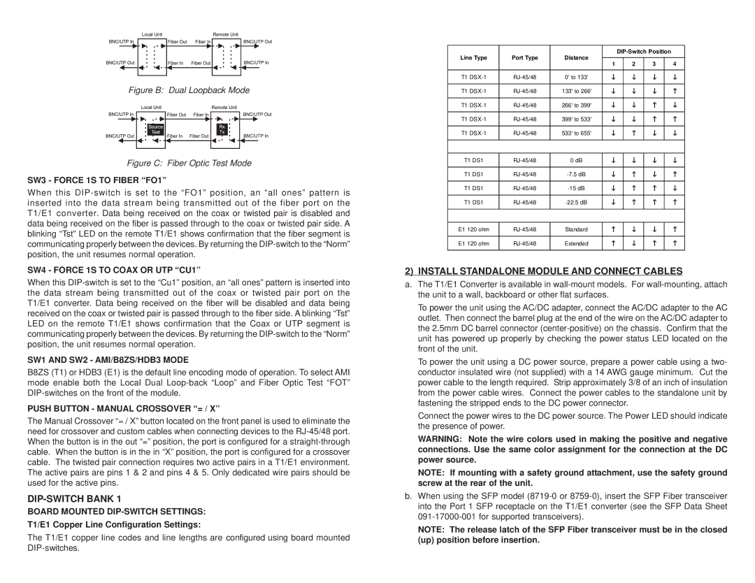
Figure B: Dual Loopback Mode

Figure C: Fiber Optic Test Mode

SW3 - FORCE 1S TO FIBER “FO1”

When this DIP-switch is set to the “FO1” position, an “all ones” pattern is inserted into the data stream being transmitted out of the fiber port on the T1/E1 converter. Data being received on the coax or twisted pair is disabled and data being received on the fiber is passed through to the coax or twisted pair side. A blinking “Tst” LED on the remote T1/E1 shows confirmation that the fiber segment is communicating properly between the devices. By returning the DIP-switch to the “Norm” position, the unit resumes normal operation.

SW4 - FORCE 1S TO COAX OR UTP “CU1”

When this DIP-switch is set to the “Cu1” position, an “all ones” pattern is inserted into the data stream being transmitted out of the coax or twisted pair port on the T1/E1 converter. Data being received on the fiber will be disabled and data being received on the coax or twisted pair is passed through to the fiber side. A blinking “Tst” LED on the remote T1/E1 shows confirmation that the Coax or UTP segment is communicating properly between the devices. By returning the DIP-switch to the “Norm” position, the unit resumes normal operation.

SW1 AND SW2 - AMI/B8ZS/HDB3 MODE

B8ZS (T1) or HDB3 (E1) is the default line encoding mode of operation. To select AMI mode enable both the Local Dual Loop-back “Loop” and Fiber Optic Test “FOT” DIP-switches on the front of the module.

PUSH BUTTON - MANUAL CROSSOVER “= / X”

The Manual Crossover “= / X” button located on the front panel is used to eliminate the need for crossover and custom cables when connecting devices to the RJ-45/48 port. When the button is in the out “=” position, the port is configured for a straight-through cable. When the button is in the in “X” position, the port is configured for a crossover cable. The twisted pair connection requires two active pairs in a T1/E1 environment. The active pairs are pins 1 & 2 and pins 4 & 5. Only dedicated wire pairs should be used for the active pins.

DIP-SWITCH BANK 1

BOARD MOUNTED DIP-SWITCH SETTINGS:

T1/E1 Copper Line Configuration Settings:

The T1/E1 copper line codes and line lengths are configured using board mounted DIP-switches.

Line Type

Port Type

Distance


DIP-Switch Position


1


2

3


4


T1 DSX-1

RJ-45/48

0' to 133'

L


L

L


L


T1 DSX-1

RJ-45/48

133' to 266'

L


L

L


K


T1 DSX-1

RJ-45/48

266' to 399'

L


L

K


L


T1 DSX-1

RJ-45/48

399' to 533'

L


L

K


K


T1 DSX-1

RJ-45/48

533' to 655'

L


K

L


L


T1 DS1

RJ-45/48

0 dB

L


L

L


L


T1 DS1

RJ-45/48

-7.5 dB

L


K

L


K


T1 DS1

RJ-45/48

-15 dB

L


K

K


L


T1 DS1

RJ-45/48

-22.5 dB

L


K

K


K


E1 120 ohm

RJ-45/48

Standard

K


L

L


K


E1 120 ohm

RJ-45/48

Extended

K


L

K


K


2) INSTALL STANDALONE MODULE AND CONNECT CABLES

a.The T1/E1 Converter is available in wall-mount models. For wall-mounting, attach the unit to a wall, backboard or other flat surfaces.

To power the unit using the AC/DC adapter, connect the AC/DC adapter to the AC outlet. Then connect the barrel plug at the end of the wire on the AC/DC adapter to the 2.5mm DC barrel connector (center-positive) on the chassis. Confirm that the unit has powered up properly by checking the power status LED located on the front of the unit.

To power the unit using a DC power source, prepare a power cable using a two- conductor insulated wire (not supplied) with a 14 AWG gauge minimum. Cut the power cable to the length required. Strip approximately 3/8 of an inch of insulation from the power cable wires. Connect the power cables to the standalone unit by fastening the stripped ends to the DC power connector.

Connect the power wires to the DC power source. The Power LED should indicate the presence of power.

WARNING: Note the wire colors used in making the positive and negative connections. Use the same color assignment for the connection at the DC power source.

NOTE: If mounting with a safety ground attachment, use the safety ground screw at the rear of the unit.

b.When using the SFP model (8719-0 or 8759-0), insert the SFP Fiber transceiver into the Port 1 SFP receptacle on the T1/E1 converter (see the SFP Data Sheet 091-17000-001 for supported transceivers).

NOTE: The release latch of the SFP Fiber transceiver must be in the closed (up) position before insertion.

Page 2
Image 2
Omnitron Systems Technology T1/E1 user manual DIP-SWITCH Bank, Install Standalone Module and Connect Cables

T1/E1 specifications

Omnitron Systems Technology's T1/E1 products represent a significant advancement in telecommunications, catering specifically to the needs of modern networks. These devices are designed to provide reliable and efficient transmission of voice, data, and video over T1/E1 lines, making them essential for businesses that require robust communication capabilities.

One of the main features of the Omnitron T1/E1 products is their ability to support both T1 and E1 formats. T1 lines are commonly used in North America and can carry 24 voice channels, while E1 lines are widely used in Europe and can carry 30 voice channels. This flexibility allows organizations to integrate their existing infrastructure seamlessly with either format, ensuring compatibility across different regions and service providers.

The technology behind Omnitron's T1/E1 products includes advanced signal processing and error correction algorithms, which enhance the quality and reliability of data transmission. These innovations ensure minimal jitter and latency, delivering smooth communication even in the most demanding environments. The devices are designed to operate over both copper and fiber optic links, giving network administrators the freedom to choose the medium that best suits their operational needs.

Another characteristic of Omnitron's T1/E1 solution is its user-friendly management features. Many devices come equipped with a web-based management interface that allows for easy configuration and monitoring of the network. This facilitates rapid troubleshooting and performance optimization, enabling IT teams to maintain uninterrupted service.

Furthermore, Omnitron’s T1/E1 products are built with scalability in mind. As businesses grow, their telecommunication needs evolve. Omnitron systems can be seamlessly integrated into larger networks or expanded as necessary, supporting more channels or additional services without requiring a complete overhaul of the existing infrastructure.

In conclusion, Omnitron Systems Technology's T1/E1 products embody cutting-edge technologies that enhance the performance and reliability of communication systems. With their capability to support both T1 and E1 formats, advanced signal processing, user-friendly management interfaces, and scalability, they are well-suited for businesses looking to optimize their network infrastructure and ensure effective communication across all channels. The reliability and versatility of these systems make them a strategic choice for organizations aiming to enhance their telecommunications capabilities in an increasingly connected world.