VI. Assembly Instructions
Fan / Blower is shipped strapped to Cyclone Barrel. It is NOT attached to the unit. You must bolt them together. Follow the instructions below.
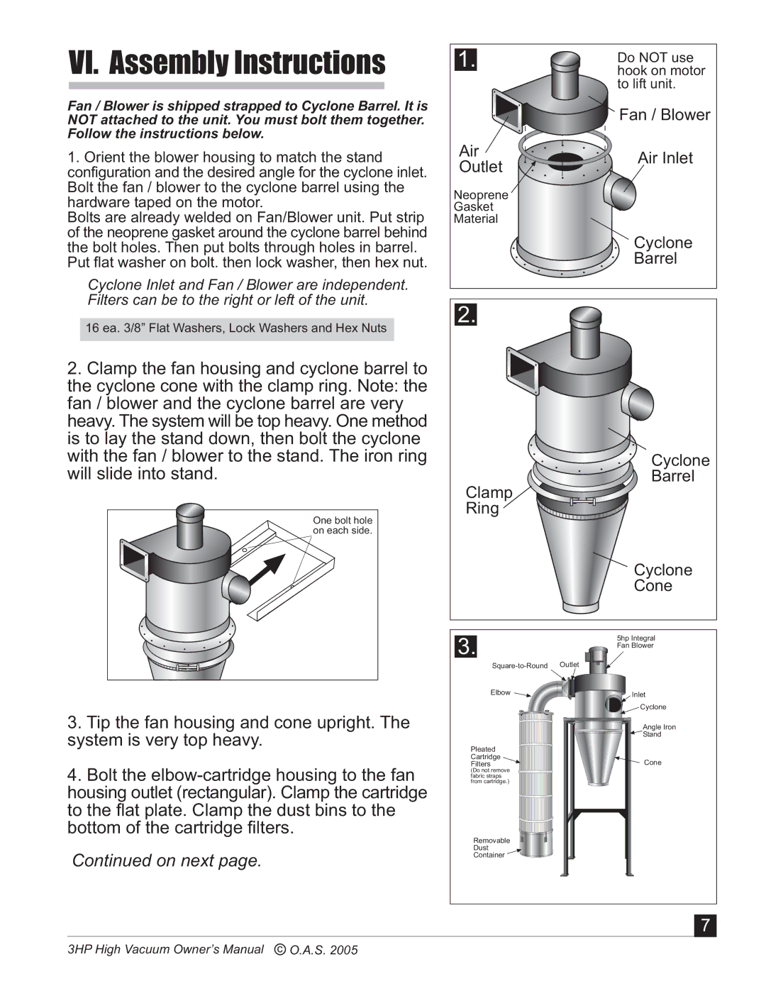
1.Orient the blower housing to match the stand configuration and the desired angle for the cyclone inlet. Bolt the fan / blower to the cyclone barrel using the hardware taped on the motor.
Bolts are already welded on Fan/Blower unit. Put strip of the neoprene gasket around the cyclone barrel behind the bolt holes. Then put bolts through holes in barrel.
Put flat washer on bolt. then lock washer, then hex nut.
Cyclone Inlet and Fan / Blower are independent. Filters can be to the right or left of the unit.
16 ea. 3/8” Flat Washers, Lock Washers and Hex Nuts
2.Clamp the fan housing and cyclone barrel to the cyclone cone with the clamp ring. Note: the fan / blower and the cyclone barrel are very heavy. The system will be top heavy. One method is to lay the stand down, then bolt the cyclone with the fan / blower to the stand. The iron ring will slide into stand.
One bolt hole on each side.
1. | Do NOT use | |
| hook on motor | |
| to lift unit. | |
| Fan / Blower | |
Air | Air Inlet | |
Outlet | ||
| ||
Neoprene |
| |
Gasket |
| |
Material |
|
Cyclone
Barrel
2.
Cyclone
Barrel
Clamp
Ring
![]() Cyclone
Cyclone
Cone
3. | 5hp Integral |
| Fan Blower |
|
3.Tip the fan housing and cone upright. The system is very top heavy.
4.Bolt the
Continued on next page.
Elbow ![]()
Pleated
Cartridge
Filters
(Do not remove fabric straps from cartridge.)
Removable
Dust
Container ![]()
![]()
Inlet |
Cyclone |
Angle Iron |
Stand |
Cone |
7
3HP High Vacuum Owner’s Manual c O.A.S. 2005