R.A. worm gear shaft ![]()
Brass gear of R.A. | Hole |
motor assembly |
Figure 3. The motor is attached to the front of the mount by a sockethead cap screw pushed up through the hole in the rear of the mount.
This attachment process is tricky, and it may take you sev- eral tries before you get it right.
3.Remove the R.A.
4.Slide the open end of the manual clutch assembly (Figure
4)onto the worm gear shaft. Rotate the manual clutch
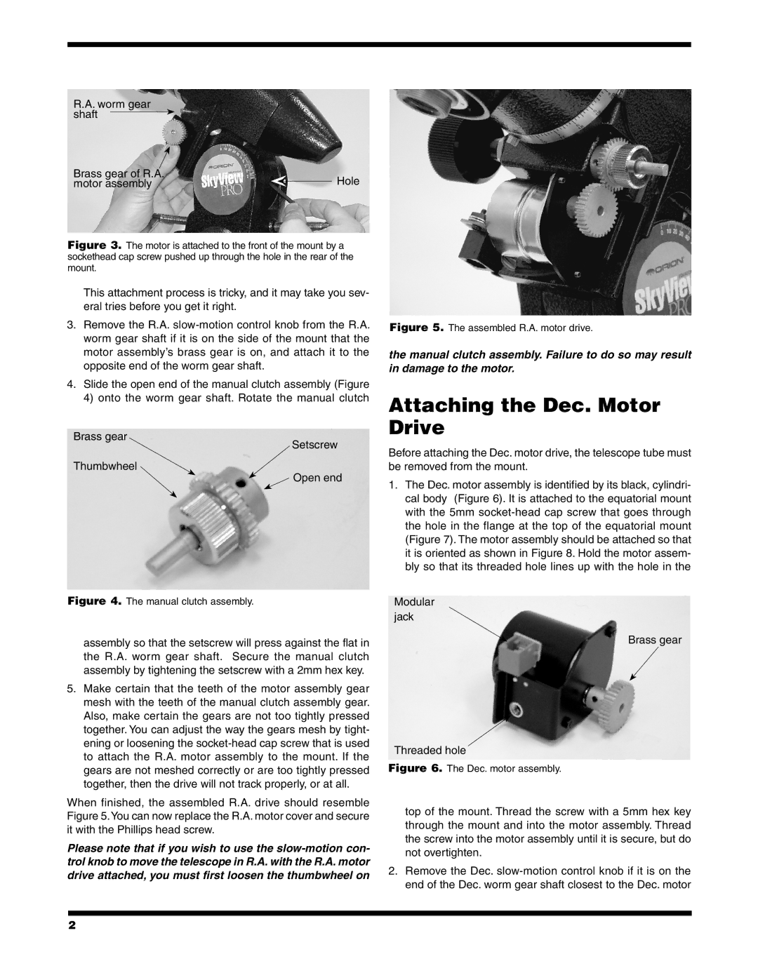
Brass gear
Setscrew
Thumbwheel
Open end
Figure 4. The manual clutch assembly.
assembly so that the setscrew will press against the flat in the R.A. worm gear shaft. Secure the manual clutch assembly by tightening the setscrew with a 2mm hex key.
5.Make certain that the teeth of the motor assembly gear mesh with the teeth of the manual clutch assembly gear. Also, make certain the gears are not too tightly pressed together. You can adjust the way the gears mesh by tight- ening or loosening the socket-head cap screw that is used to attach the R.A. motor assembly to the mount. If the gears are not meshed correctly or are too tightly pressed together, then the drive will not track properly, or at all.
When finished, the assembled R.A. drive should resemble Figure 5.You can now replace the R.A. motor cover and secure it with the Phillips head screw.
Please note that if you wish to use the
Figure 5. The assembled R.A. motor drive.
the manual clutch assembly. Failure to do so may result in damage to the motor.
Attaching the Dec. Motor Drive
Before attaching the Dec. motor drive, the telescope tube must be removed from the mount.
1.The Dec. motor assembly is identified by its black, cylindri- cal body (Figure 6). It is attached to the equatorial mount with the 5mm
Modular jack
Brass gear
Threaded hole
Figure 6. The Dec. motor assembly.
top of the mount. Thread the screw with a 5mm hex key through the mount and into the motor assembly. Thread the screw into the motor assembly until it is secure, but do not overtighten.
2.Remove the Dec.
2