3. Assembly
Assembling the telescope for the first time should take about 30 minutes. No tools are needed other than the ones provid- ed. All bolts should be tightened securely to eliminate flexing and wobbling, but be careful not to
During assembly (and anytime, for that matter), DO NOT touch the surface of the telescope’s meniscus lens or the lenses of the finder scopes or eyepieces with your fingers. The optical surfaces have delicate coatings on them that can easily be damaged if touched inappropriately. NEVER remove any lens assembly from its housing for any reason, or the product warranty and return policy will be voided.
1.Lay the equatorial mount on its side. Attach the tripod legs one at a time to the mount by sliding the bolts installed in the tops of the tripod legs into the slots at the base of the mount and tightening the wing nuts
2.Tighten the leg lock knobs on the bottom braces of the tri- pod legs. For now, keep the legs at their shortest (fully retracted) length; you can extend them to a more desirable length later, after the telescope is completely assembled.
3.With the tripod legs now attached to the equatorial mount, stand the tripod upright (be careful!) and spread the legs
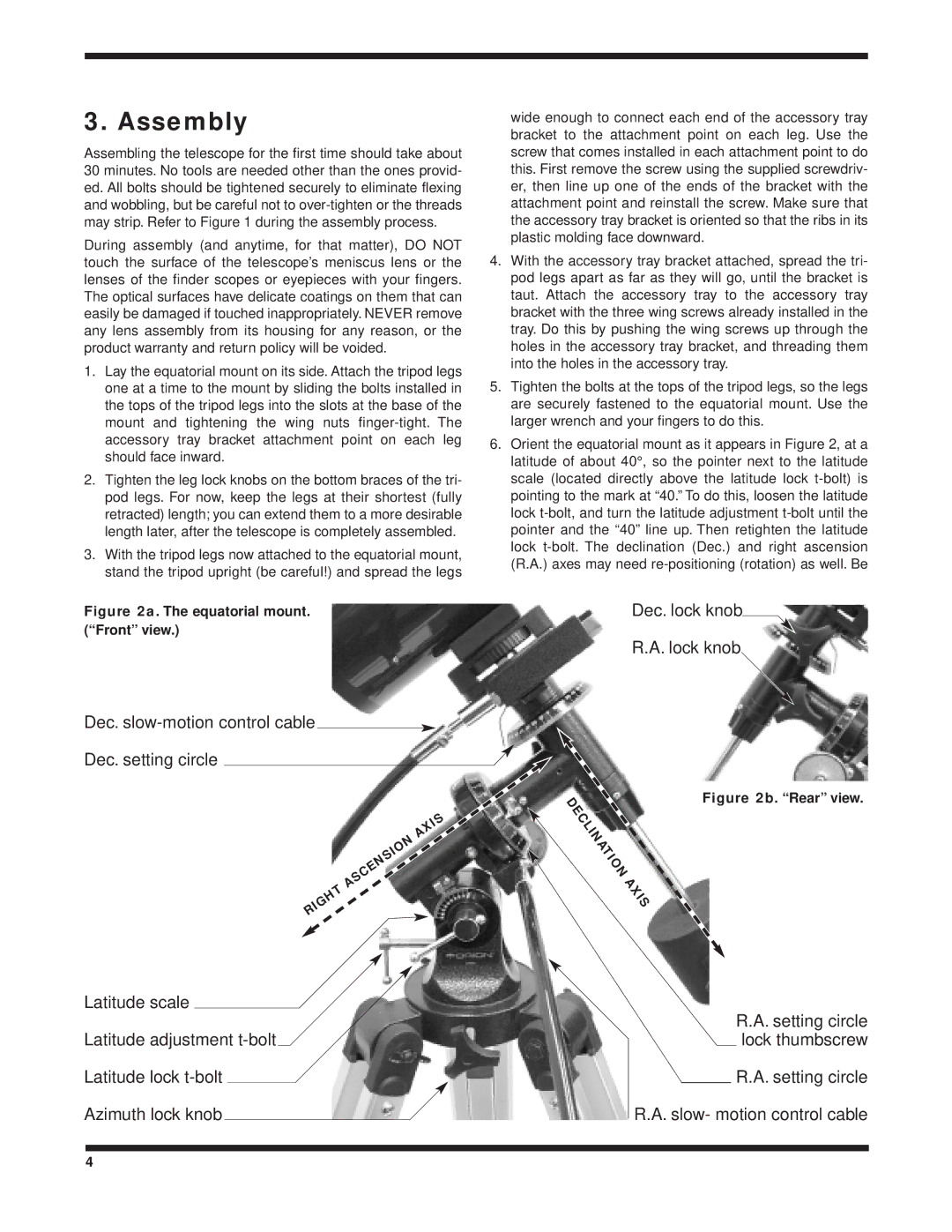
Figure 2a. The equatorial mount. (“Front” view.)
Dec. slow-motion control cable
Dec. setting circle
| IS |
| X |
N | A |
| |
IO |
|
S |
|
N |
|
E |
|
C |
|
S |
|
A |
|
T |
|
H |
|
IG |
|
R |
|
wide enough to connect each end of the accessory tray bracket to the attachment point on each leg. Use the screw that comes installed in each attachment point to do this. First remove the screw using the supplied screwdriv- er, then line up one of the ends of the bracket with the attachment point and reinstall the screw. Make sure that the accessory tray bracket is oriented so that the ribs in its plastic molding face downward.
4.With the accessory tray bracket attached, spread the tri- pod legs apart as far as they will go, until the bracket is taut. Attach the accessory tray to the accessory tray bracket with the three wing screws already installed in the tray. Do this by pushing the wing screws up through the holes in the accessory tray bracket, and threading them into the holes in the accessory tray.
5.Tighten the bolts at the tops of the tripod legs, so the legs are securely fastened to the equatorial mount. Use the larger wrench and your fingers to do this.
6.Orient the equatorial mount as it appears in Figure 2, at a latitude of about 40°, so the pointer next to the latitude scale (located directly above the latitude lock
Dec. lock knob
R.A. lock knob
D | Figure 2b. “Rear” view. |
E |
|
C |
|
L |
|
IN |
|
A |
|
T |
|
IO |
|
N |
|
A |
|
X |
|
IS |
|
Latitude scale
Latitude adjustment
R.A. setting circle lock thumbscrew
R.A. setting circle
R.A. slow- motion control cable
4