down much too freely. This causes problems when the observ- er tries to accurately center and track an object for viewing, especially at higher powers. Also, the telescope becomes very sensitive to balance, requiring additional equipment such as counterweight systems or springs to compensate.
SkyQuest Intelliscope Dobsonians employ a simple yet effec- tive remedy for the friction problem that obviates the need for such cumbersome countermeasures. CorrecTension Friction
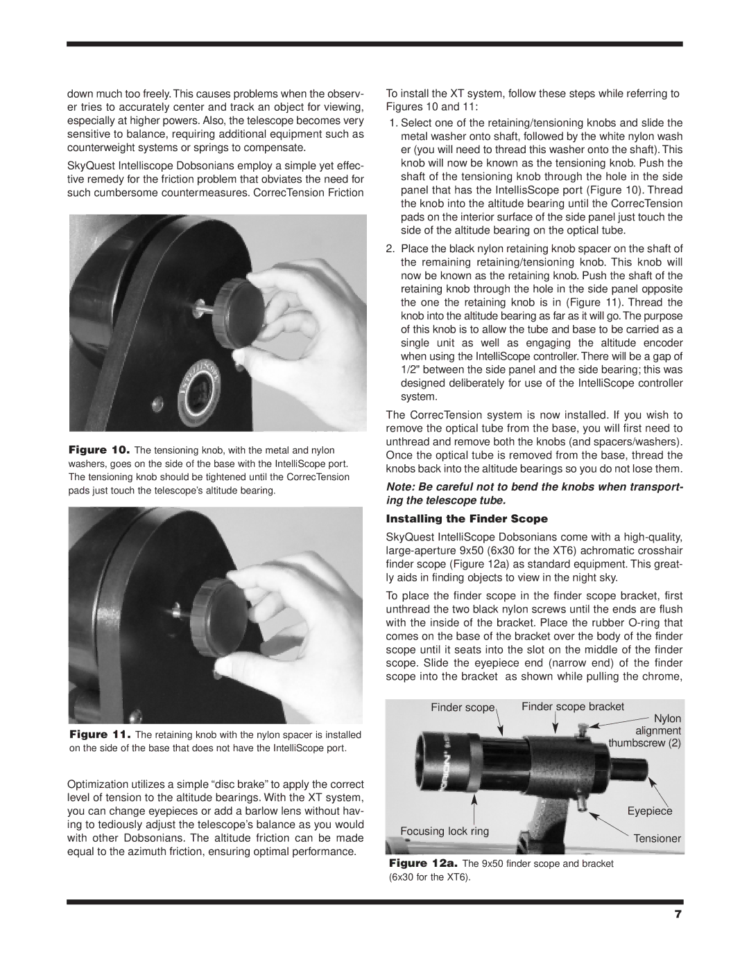
Figure 10. The tensioning knob, with the metal and nylon washers, goes on the side of the base with the IntelliScope port. The tensioning knob should be tightened until the CorrecTension pads just touch the telescope’s altitude bearing.
Figure 11. The retaining knob with the nylon spacer is installed on the side of the base that does not have the IntelliScope port.
Optimization utilizes a simple “disc brake” to apply the correct level of tension to the altitude bearings. With the XT system, you can change eyepieces or add a barlow lens without hav- ing to tediously adjust the telescope’s balance as you would with other Dobsonians. The altitude friction can be made equal to the azimuth friction, ensuring optimal performance.
To install the XT system, follow these steps while referring to Figures 10 and 11:
1.Select one of the retaining/tensioning knobs and slide the metal washer onto shaft, followed by the white nylon wash er (you will need to thread this washer onto the shaft). This knob will now be known as the tensioning knob. Push the shaft of the tensioning knob through the hole in the side panel that has the IntellisScope port (Figure 10). Thread the knob into the altitude bearing until the CorrecTension pads on the interior surface of the side panel just touch the side of the altitude bearing on the optical tube.
2.Place the black nylon retaining knob spacer on the shaft of the remaining retaining/tensioning knob. This knob will now be known as the retaining knob. Push the shaft of the retaining knob through the hole in the side panel opposite the one the retaining knob is in (Figure 11). Thread the knob into the altitude bearing as far as it will go. The purpose of this knob is to allow the tube and base to be carried as a single unit as well as engaging the altitude encoder when using the IntelliScope controller. There will be a gap of 1/2" between the side panel and the side bearing; this was designed deliberately for use of the IntelliScope controller system.
The CorrecTension system is now installed. If you wish to remove the optical tube from the base, you will first need to unthread and remove both the knobs (and spacers/washers). Once the optical tube is removed from the base, thread the knobs back into the altitude bearings so you do not lose them.
Note: Be careful not to bend the knobs when transport- ing the telescope tube.
Installing the Finder Scope
SkyQuest IntelliScope Dobsonians come with a
To place the finder scope in the finder scope bracket, first unthread the two black nylon screws until the ends are flush with the inside of the bracket. Place the rubber
Finder scope | Finder scope bracket |
| Nylon |
| alignment |
| thumbscrew (2) |
Eyepiece
Focusing lock ring
Tensioner
Figure 12a. The 9x50 finder scope and bracket (6x30 for the XT6).
7