END PANEL LAYOUTS
1 | 2 | 3 | 4 |
| 5 | 6 | 7 | 8 | 9 | 10 |
INPUT | LINE OUT |
|
|
|
| INTELLI |
|
|
| POWER |
L CH | L CH |
| GAIN | INFRASONIC | LPF | REMOTE | PHASE | (GREEN) | ||
| BASS |
| ||||||||
|
|
|
| |||||||
| MASTER |
| SLAVE | ON | OFF |
|
| Oº |
| 180º |
|
|
| MIN MAX |
|
| MIN MAX | 30Hz 250Hz |
|
| PROTECT |
|
|
|
|
|
|
|
|
|
| (RED) |
R CH | R CH |
|
|
|
|
|
|
|
|
|
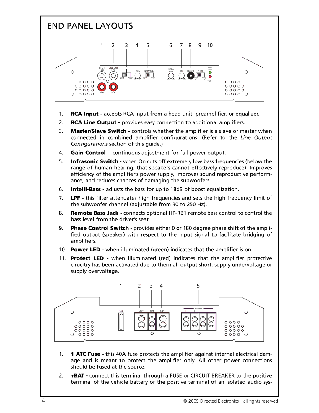
1.RCA Input - accepts RCA input from a head unit, preamplifier, or equalizer.
2.RCA Line Output - provides easy connection to additional amplifiers.
3.Master/Slave Switch - controls whether the amplifier is a slave or master when connected in combined amplifier configurations. (Refer to the Line Output Configurations section of this guide.)
4.Gain Control - continuous adjustment for full power output.
5.Infrasonic Switch - when On cuts off extremely low bass frequencies (below the range of human hearing, that speakers cannot effectively reproduce). Improves efficiency of the amplifier’s power supply, improves sound reproductive perform- ance, and reduces chances of damaging the subwoofers.
6.
7.LPF - this filter attenuates high frequencies and sets the high frequency limit of the subwoofer channel (adjustable from 30 to 250 Hz).
8.Remote Bass Jack - connects optional
9.Phase Control Switch - provides either 0 or 180 degree phase shift of the ampli- fied output (speaker) with respect to the input signal to facilitate bridging of amplifiers.
10.Power LED - when illuminated (green) indicates that the amplifier is on.
11.Protect LED - when illuminated (red) indicates that the amplifier protective cirucitry has been activated due to thermal, output short, supply undervoltage or supply overvoltage.
1 | 2 | 3 | 4 | 5 | |||||
|
|
|
|
|
|
|
|
|
|
|
|
|
|
|
|
|
| SPEAKER | |
|
|
|
|
|
|
|
| ||
FUSE | +BAT | REM | GND | + + - - | |||||
|
|
|
|
|
|
|
|
|
|
1.1 ATC Fuse - this 40A fuse protects the amplifier against internal electrical dam- age and is meant to protect the amplifier only. All other power connections should be fused at the source.
2.+BAT - connect this terminal through a FUSE or CIRCUIT BREAKER to the positive terminal of the vehicle battery or the positive terminal of an isolated audio sys-
4 | © 2005 Directed |
