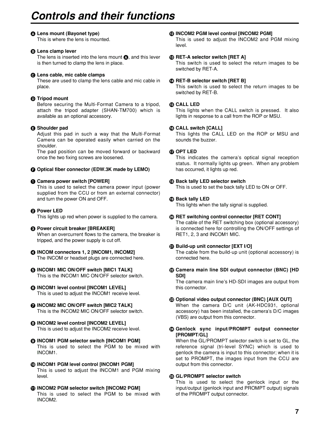
Controls and their functions
A Lens mount (Bayonet type)
This is where the lens is mounted.
B Lens clamp lever
The lens is inserted into the lens mount A, and this lever is then turned to clamp the lens in place.
C Lens cable, mic cable clamps
These are used to clamp the lens cable and mic cable in place.
D Tripod mount
Before securing the
E Shoulder pad
Adjust this pad in such a way that the
The pad position can be moved forward or backward once the two fixing screws are loosened.
F Optical fiber connector (EDW.3K made by LEMO)
1 Camera power switch [POWER]
This is used to select the camera power input (power supplied from the CCU or from an external connector) and turn the power ON and OFF.
2 Power LED
This lights up red when power is supplied to the camera.
3 Power circuit breaker [BREAKER]
When an overcurrent flows to the camera, the breaker is tripped, and the power supply is cut off.
4 INCOM connectors 1, 2 [INCOM1, INCOM2]
The INCOM or headset plugs are connected here.
5 INCOM1 MIC ON/OFF switch [MIC1 TALK]
This is the INCOM1 MIC ON/OFF selector switch.
6 INCOM1 level control [INCOM1 LEVEL]
This is used to adjust the INCOM1 receive level.
7 INCOM2 MIC ON/OFF switch [MIC2 TALK]
This is the INCOM2 MIC ON/OFF selector switch.
8 INCOM2 level control [INCOM2 LEVEL]
This is used to adjust the INCOM2 receive level.
9 INCOM1 PGM selector switch [INCOM1 PGM]
This is used to select the PGM to be mixed with INCOM1.
:INCOM1 PGM level control [INCOM1 PGM]
This is used to adjust the INCOM1 and PGM mixing level.
;INCOM2 PGM selector switch [INCOM2 PGM]
This is used to select the PGM to be mixed with INCOM2.
<INCOM2 PGM level control [INCOM2 PGM]
This is used to adjust the INCOM2 and PGM mixing level.
=RET-A selector switch [RET A]
This switch is used to select the return images to be switched by
>RET-B selector switch [RET B]
This switch is used to select the return images to be switched by
?CALL LED
This lights when the CALL switch is pressed. It also lights in response to a call from the ROP or MSU.
@CALL switch [CALL]
This lights the CALL LED on the ROP or MSU and sounds the buzzer.
A OPT LED
This indicates the camera’s optical signal reception status. It normally lights up green. When any problem has occurred, it lights up red.
B Back tally LED selector switch
This is used to set the back tally LED to ON or OFF.
C Back tally LED
This lights when the tally signal is supplied.
D RET switching control connector [RET CONT]
The cable of the RET switching box (optional accessory) is connected here for controlling the ON/OFF settings of RET1, 2, 3 and INCOM1 MIC.
E Build-up unit connector [EXT I/O]
The cable from the
F Camera main line SDI output connector (BNC) [HD SDI]
The camera main line’s
G Optional video output connector (BNC) [AUX OUT]
When the camera D/C unit
H Genlock sync input/PROMPT output connector [PROMPT/GL]
When the GL/PROMPT selector switch is set to GL, the reference signal
I GL/PROMPT selector switch
This is used to select the genlock input or the input/output (genlock input and PROMPT output) signals of the PROMPT output connector.
7