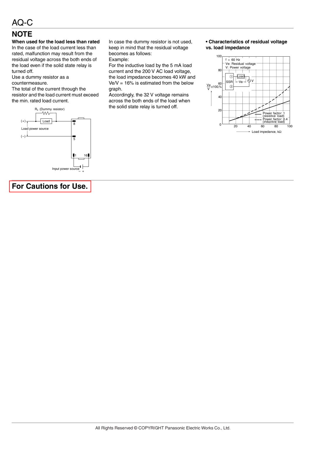
AQ-C Relays specifications
The Panasonic AQ-C series of relays represents a significant advancement in relay technology, offering robust performance and reliability for a variety of applications. These relays are designed to cater to the demands of modern electronic systems, making them an ideal choice for industries ranging from automotive to industrial automation and consumer electronics.One of the main features of the AQ-C relays is their compact size combined with high switching capacity. This allows them to be integrated easily into space-constrained designs without compromising on performance. The AQ-C relays support a switching capacity of up to 30A, making them suitable for controlling high-power devices. This high capacity is particularly beneficial in automotive applications where reliable power management is crucial.
The AQ-C series utilizes unique contact materials and configurations to enhance durability and minimize contact bounce. This technology significantly extends the operational life of the relay, allowing it to withstand millions of switching cycles. Furthermore, the relays are designed to have a low power consumption during operation, which helps to improve energy efficiency in applications where power consumption is a critical factor.
In terms of thermal management, the AQ-C relays feature excellent heat dissipation properties. This is essential in high-temperature environments, as it ensures the relay operates reliably without overheating. Additionally, the relays are available in both normally-open and normally-closed configurations, providing flexibility to designers based on their specific circuit requirements.
The AQ-C series is manufactured to meet rigorous quality standards, ensuring they are resilient against harsh conditions. With a wide operating temperature range, these relays can function effectively in extreme environments, making them suitable for outdoor and industrial applications.
Innovative manufacturing processes have been employed to enhance the reliability of the AQ-C relays further. These processes include automated quality control checks and enhanced testing protocols to ensure each relay meets the highest standards before it reaches the market. The result is a product line that not only meets but often exceeds industry expectations for performance and durability.
Overall, the Panasonic AQ-C relays combine advanced technologies with superior design to provide a reliable solution for demanding applications. Their impressive features make them an excellent choice for engineers and designers seeking high-performance relay solutions across various sectors. Whether for automotive applications, industrial controls, or consumer electronics, the AQ-C series is a testament to Panasonic's commitment to quality and innovation in relay technology.

