Notebook Computer
H Smart Card Reader, Finger Print Reader Configurated
This is the Service Manual for the following areas
Model No. CF-52EKMxDxM
How to replace the fuse
For U.K
This apparatus must be earthed for your safety
For U.S.A
LASER SAFETY INFORMATION
LITHIUM BATTERY
SAFETY PRECAUTIONS
LITHIUM BATTERY
Important Safety Instructions
Do Not Use with Any Other Product
Precautions Battery Pack
Appendix Troubleshooting Useful Information Getting Started
Do Not Charge the Battery Using Methods Other Than Those Specified
CONTENTS
Model No
1. Specifications
Intel WiFi Link
Bluetooth *14
OS*25
Software
Wireless LAN
Bluetooth Only for model with Bluetooth
depending on writing status and recording format. Also, some
Reference Manual “Wireless LAN”
2. Names and Functions of Parts
Specified Battery pack CF-VZSU29ASU
Only for model with wireless LAN/wireless WAN
F H I J L M N
A B C
Processor
FingerPrint Bluetooth
uFCBGA
L2 Cache 4M Clock Speed 2GHz
4 Diagnosis Procedure
Flow Chart
4.2. Troubleshooting
5 Power-On Self Test Boot Check
Error Diagnosis by Checking Beep Signal Sound
Outline of POST
6 List of Error Codes Only when the port replicator is connected
02D0 System cache error - Cache disabled
1-3. When you execute the enhancing test
7 Self Diagnosis Test
1. Beginning of self-diagnosis test 1-1. Setting of content of setup
1-2. When you execute an automatic test
2. Operation of PC-Diagnostic Utility
2-2. PC-Diagnostic utility End method
2-3. The content of the setup is returned to the setting of the user
2-1. Selection of tested device
All memory space is tested in a special
3. Test Item and Division of trouble
Place with possibili
ty of breakdown
Test Item
8 Wiring Connection Diagram
9 Disassembly/Reassembly
9.1. Disassembly Instructions
9.1.1. Disassembly Flowchart
9.1.3.3. DVD Multi Drive
9.1.3.1. Battery Pack
9.1.2. Preparation
9.1.3.2. HDD Mounting Kit
9.1.7. Removing the ROBSON Cover, Wireless LAN Module and BIOS PCB
9.1.5. Removing the Tilt Panl Ass’y
9.1.6. Removing the DIMM Memory Card
9.1.7.1. Wireless LAN Module
9.1.7.2. BIOS PCB
9.1.8. Removing the Display unit
9.1.10. Removing the Handle Assy
9.1.9. Removing the LCD unit, Inverter Ass’y and ANTENNA PWB L,R
9.1.13. Removing the Keyboard
9.1.11. Removing the Modem
9.1.12.2. Speaker R
9.1.12.3. Speaker L
Cover
9.1.14. Removing the Top Cover
9.1.15. Removing the Pad and TOUCH PAD PCB
9.1.16. Removing the SD PCB
9.1.19. Removing the PWR BATTERY LED PCB
9.1.17. Removing the WWAN PCB
9.1.18. Removing the AUDIO PCB
Cover PC card
9.1.20. Removing the KBD Earth Plate
9.1.21. Removing the Hinge Support R
9.1.22. Removing the Fan Ass’y
9.1.26. Removing the Heat Sink Ass’y
9.1.24. Removing the Battery Connector Ass’y
9.1.23. Removing the Hinge Support L and MP Hold Plate
9.1.25. Removing the SC RELAY PCB and HDD Hold Plate
9.1.28. Removing the MAIN HIGH PCB
9.1.27. Removing the SERIAL PCB
9.2. Reassembly Instructions
9.2.1. Attention when CF-52 series is repaired
9.2.2. Setting the MAIN HIGH PCB
S1Insulation S2Bitten S3Sharp Edge S4Part No. Check S5Other
Setting of Main PCB before assembling
S4Part No. Check S5Other
THERMAL SHEET SCREW
Torque of tightening screw 0.18±0.02N・m≒1.8±0.2kgf・cm
THERMAL SHEET
9.2.3. Setting the SERIAL PCB
9.2.4. Setting the Heat Sink Ass’y
Hex spacer No.3
How to assemble the Heat Sink Ass’y and Fan Ass’y
9.2.5. Setting the Fan Ass’y
No.1
9.2.6. Setting the SC RELAY PCB and HDD Hold Plate
SC RELAY PCB
HDD hold plate
S4Part No. Check S5Other
9.2.8. Setting the Hinge Support L and MP Hold Plate
9.2.7. Setting the Battery Connector Ass’y
How to place the Cable
9.2.9. Setting the Hinge Cover R
4. Paste the tape, and connect the FPC to the ConnectorCN34
9.2.10. Setting the KBD Earth Plate
2. Fix the KBD Earth Plate using the four Screws N4. No.1 to No.4
3. Fix the KBD Earth Plate using the two ScrewsN13
9-22
9.2.11. Setting the PWR BATTERY LED PCB
Arranging the Cable and setting the WL button
9.2.12. Setting the AUDIO PCB
Arranging the Cables and Tapes
9.2.13. Setting the WWAN PCB
9.2.15. Setting the Pad and TOUCH PAD PCB
9.2.14. Setting the SD PCB
9.2.16. Setting the Top Cover
9-27
9.2.17. Setting the Keyboard
1. Connect the FPCs to the Connector on the KBD FPC
Tape Tape Screws N2 DFHE5122YA
Caution for when assembling the Keyboard
9.2.19. Setting the Modem
9.2.18. Setting the Speakers
How to paste the Tape
9.2.20. Setting the Handle Ass’y
9.2.21. Setting the LCD Unit, Inverter Ass’y and Antenna PWB L, R
SHIELD SHEET A LCD
Using JIG
Using JIG
Schematic for sticking at Point A
LCD DAMPER E
The Cable is under the base plate Along the slot
Along the slot
TAPE
LCD ASSY
Refer to the specification pictures on the left
Safety Critical Components
SHEET
Page
9.2.22. Setting the Display Unit, BIOS HIGH PCB and SW LED MDC PCB
9-38
6. Fix the SW LED MDC PCB using the six Screws N2. No.1 to No.6
Arranging the Cables when assembling the LCD Unit
ScrewN2 DFHE5122YA Screw N4 DRHM0093ZA
Page
Arranging the Speaker Cables when assembling the SW LED MDC PCB
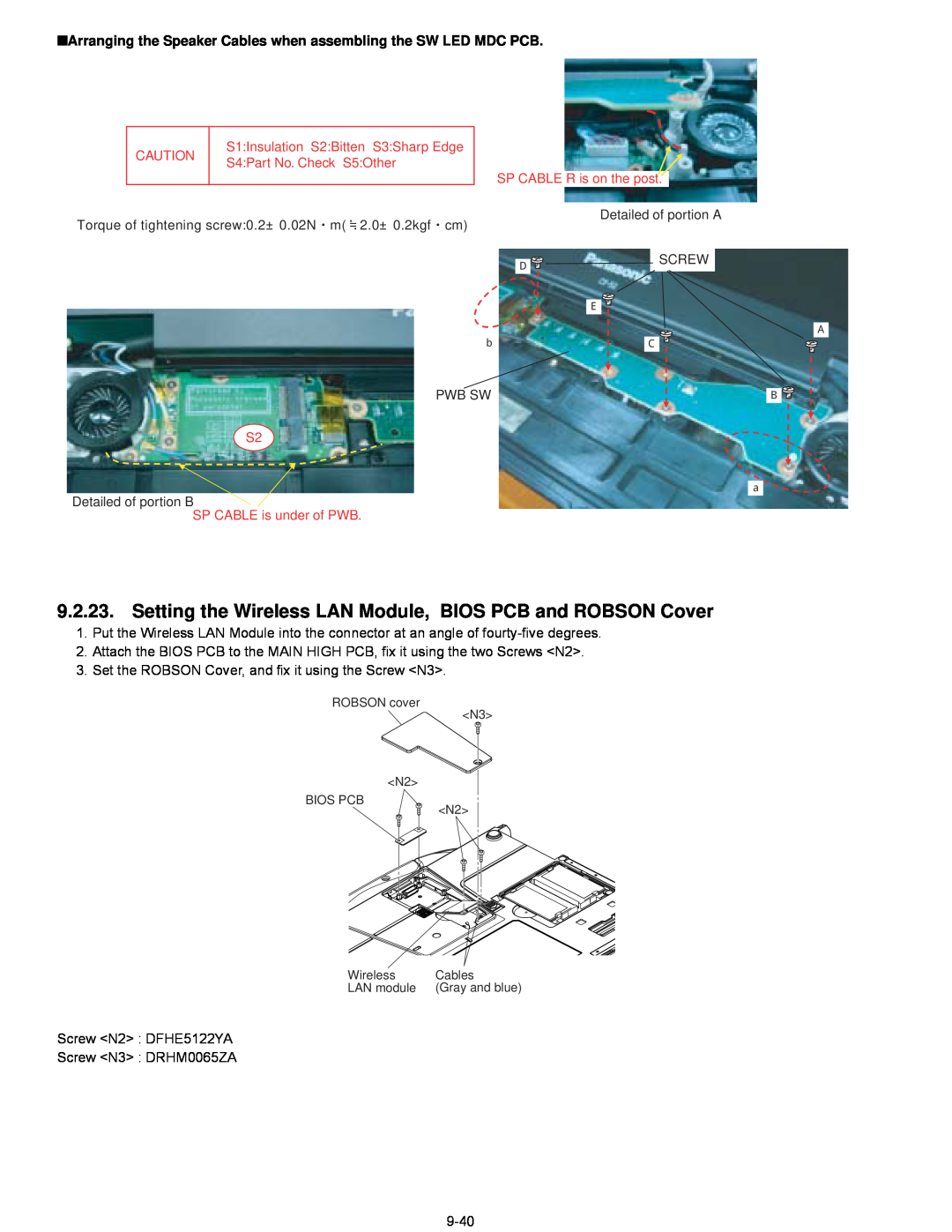
9.2.23. Setting the Wireless LAN Module, BIOS PCB and ROBSON Cover
9.2.25. Setting the Tilt Panel Ass’y
9.2.24. Setting the DIMM Memory Card and DIMM Cover
Caution for when assembling the Tilt Panel Ass’y
Screw N202 DRSB2+4FKLT
9-42
3. Set the HDD Ass’y into the HDD Case Upper
9.2.26. Setting the HDD
1. Connect the HDD FPC Ass’y to the HDD
2. Insert the HDD Ass’y into the HDD Damper
CF-52EKMxDxM
10 Exploded View
Screw tightening torque
CF-52EKMHDxM with Smart Card Reader and Finger Print Reader only SF2
A SF7 SF3 A SF8 A SF8 SF6 SF4 SF5 SF1
A 0.18 ± 0.02 N.m 1.8 ± 0.2 kgf.cm B 0.18 ± 0.01 N.m 1.8 ± 0.1 kgf.cm
Screw tightening torque
K92-2
K92-1
4.4 ± 0.2 kgf.cm
REF. NO and AREA
Replacement Parts List
Accessories
CF-52EKMxDxM
Mechanical Parts
Packing Material
K92-1
K125
DVD MULTI DRIVE
CF-52EKMHDxM
Smart
Card Reader, Finger Print Reader
MAIN PCB HIGH
DESCRIPTION
529, 530, 531, 532
502, 503, 506, 508
512, 513, 514, 515
522, 523, 524, 525
146, 148, 165, 242
C 100, 102, 120, 121
F1G0J105A001
CAPACITOR, 6.3V, 1µF
F1G1H181A495
CONNECTOR
CONNECTOR, USB
1010
IC, SWITCH
POWER MANAGEMENT SWTICH
IC, FET SWITCH
IC, USB POWER SW
IC, LINER
DC POWER LINE BEADS
DC POWER LINE INDUCTOR
C0DBDJH00009
Q 1004, 1005, 1006
B1DHDC000028
Q 1001
B1CFRD000009
424, 425, 445, 499
R 103, 107, 363, 365
D0GA472JA023
RESISTOR, 1/16W, 4.7KO
RESISTOR, 1/8W, 1O
D1BA4530A023
D0GA121JA023
D0GD1R0JA052
AUDIO PCB
SW LED PCB
PWR BATTERY PCB
SERIAL PCB
TOUCH PAD PCB
WLAN ANTENNA R PCB
BIOS PCB HIGH
BLUETOOTH PCB
WWAN PCB