Electrical Connections
![]() Caution
Caution
•This wiring information is for experienced technical individual, for safety reason, please your dealer wire this connection.
•This product is designed to operate with a 12 V DC, negative ground battery system.
•To prevent damage to the unit, be sure to follow the connection diagram below.
•Do not insert the power connector into the unit until the wiring is completed.
•Be sure to insulate any exposed wires from a possible
•Remember, if your vehicle has a drive computer or a navigation computer, the data of its memory maybe erased when the bat- tery terminals are disconnected.
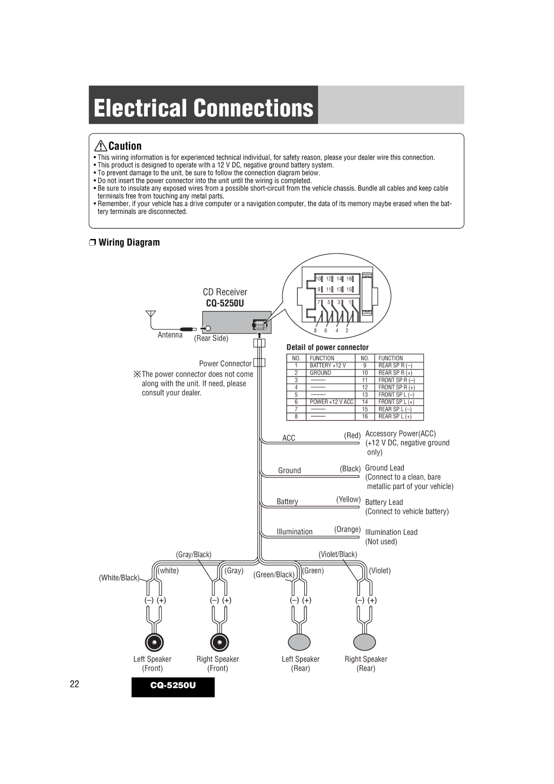
❐Wiring Diagram
| CD Receiver |
|
|
Antenna | (Rear Side) |
| |
| Power Connector |
The power connector does not come along with the unit. If need, please consult your dealer.
| 10 | 12 | 14 | 16 |
|
|
|
|
|
|
|
|
|
|
|
|
|
|
|
|
| ||||
| 9 | 11 | 13 | 15 |
|
|
|
|
|
|
|
|
| 7 | 5 | 3 | 1 |
|
|
|
|
|
|
|
|
| 8 | 6 | 4 | 2 |
|
|
|
|
|
|
|
|
|
|
|
|
|
|
|
|
| ||||
Detail of power connector |
| |||||||||||
|
|
|
|
|
|
|
|
|
|
|
| |
NO. | FUNCTION |
|
| NO. | FUNCTION | |||||||
1 | BATTERY +12 V | 9 |
|
|
| REAR SP R | ||||||
2 | GROUND |
|
| 10 |
|
|
| REAR SP R (+) | ||||
3 |
|
|
|
| 11 |
|
|
| FRONT SP R | |||
4 |
|
|
|
| 12 |
|
|
| FRONT SP R (+) | |||
5 |
|
|
|
| 13 |
|
|
| FRONT SP L | |||
6 | POWER +12 V ACC | 14 |
|
|
| FRONT SP L (+) | ||||||
7 |
|
|
|
| 15 |
|
|
| REAR SP L | |||
8 |
|
|
|
| 16 |
|
|
| REAR SP L (+) | |||
(Red) Accessory Power(ACC)
ACC
(+12 V DC, negative ground only)
Ground
Battery
(Black) Ground Lead (Connect to a clean, bare metallic part of your vehicle)
(Yellow) Battery Lead
(Connect to vehicle battery)
|
| Illumination | (Orange) | Illumination Lead | |
|
|
|
|
| (Not used) |
(Gray/Black) |
|
|
| (Violet/Black) |
|
(white) | (Gray) | (Green/Black) | (Green) | (Violet) | |
(White/Black) |
|
|
|
| |
|
|
|
|
| |
Left Speaker | Right Speaker | Left Speaker | Right Speaker |
(Front) | (Front) | (Rear) | (Rear) |
22