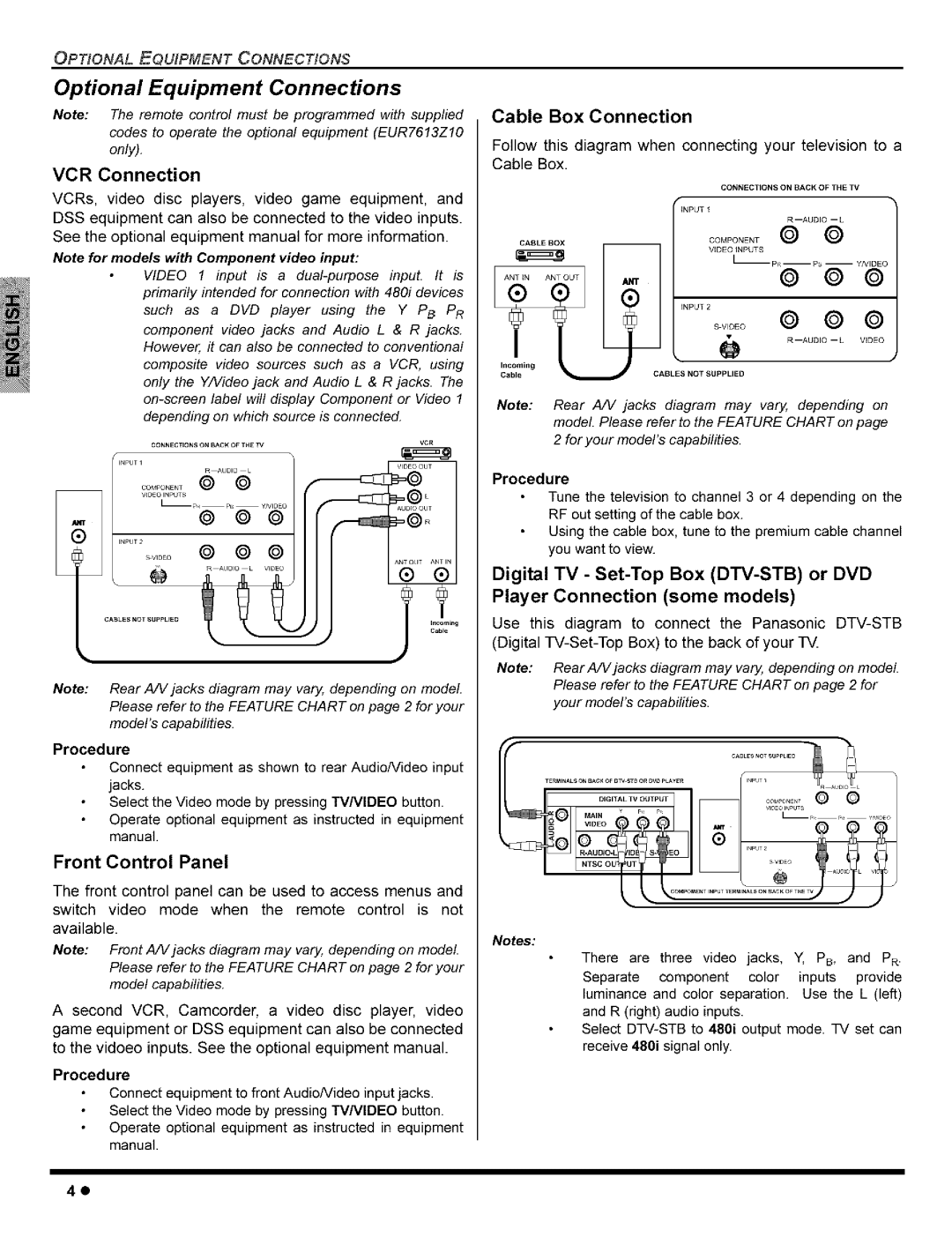
CT-27G8, CT-27C8, CT-36G8, CT-32G8, CT-32C8 specifications
Panasonic has a rich history in the realm of television technology, and models such as the CT-32C8, CT-32G8, CT-36G8, CT-27C8, and CT-27G8 showcase the brand's commitment to delivering quality and innovation. These CRT televisions, particularly popular in the early 2000s, reflect a time when picture quality and reliability took center stage in home entertainment.The CT-32C8 is a 32-inch screen that offers vibrant color reproduction and impressive detail. It features Panasonic's advanced picture technology, which enhances image clarity and reduces the occurrence of blurring during high-motion scenes. The model also comes equipped with various connectivity options, allowing enthusiasts to connect multiple devices, including DVD players and gaming consoles.
Similarly, the CT-32G8 boasts a larger 32-inch screen but elevates the experience with enhanced sound quality. This model includes a built-in surround sound system, thus providing a more immersive audiovisual experience. The display utilizes a high-contrast picture tube, which ensures deeper blacks and bright colors, making it ideal for movie nights or gaming sessions.
For those who crave a larger viewing experience, the CT-36G8 features a robust 36-inch display. This model stands out with its impressive screen size coupled with advanced resolution technology that optimizes picture quality. The CT-36G8 is engineered for larger living spaces and brings a cinematic experience to the home.
On the smaller end, the CT-27C8 and CT-27G8 both present a 27-inch viewing size. The CT-27C8 is designed with space-saving in mind, allowing it to fit comfortably in smaller rooms while still producing quality images. It features a straightforward design and user-friendly interface, making it accessible for all family members.
Conversely, the CT-27G8 offers similar dimensions but enhances the audio experience with its dynamic sound settings. This model is perfect for casual viewing while maintaining an excellent sound profile.
All five models share key characteristics that include reliable build quality and durability, making them trustworthy options for a wide range of viewers. While these TVs may not boast the modern features found in smart TVs today, they provide a nostalgic viewing experience with solid engineering that ensures high performance over time.