EJ (AEJ)
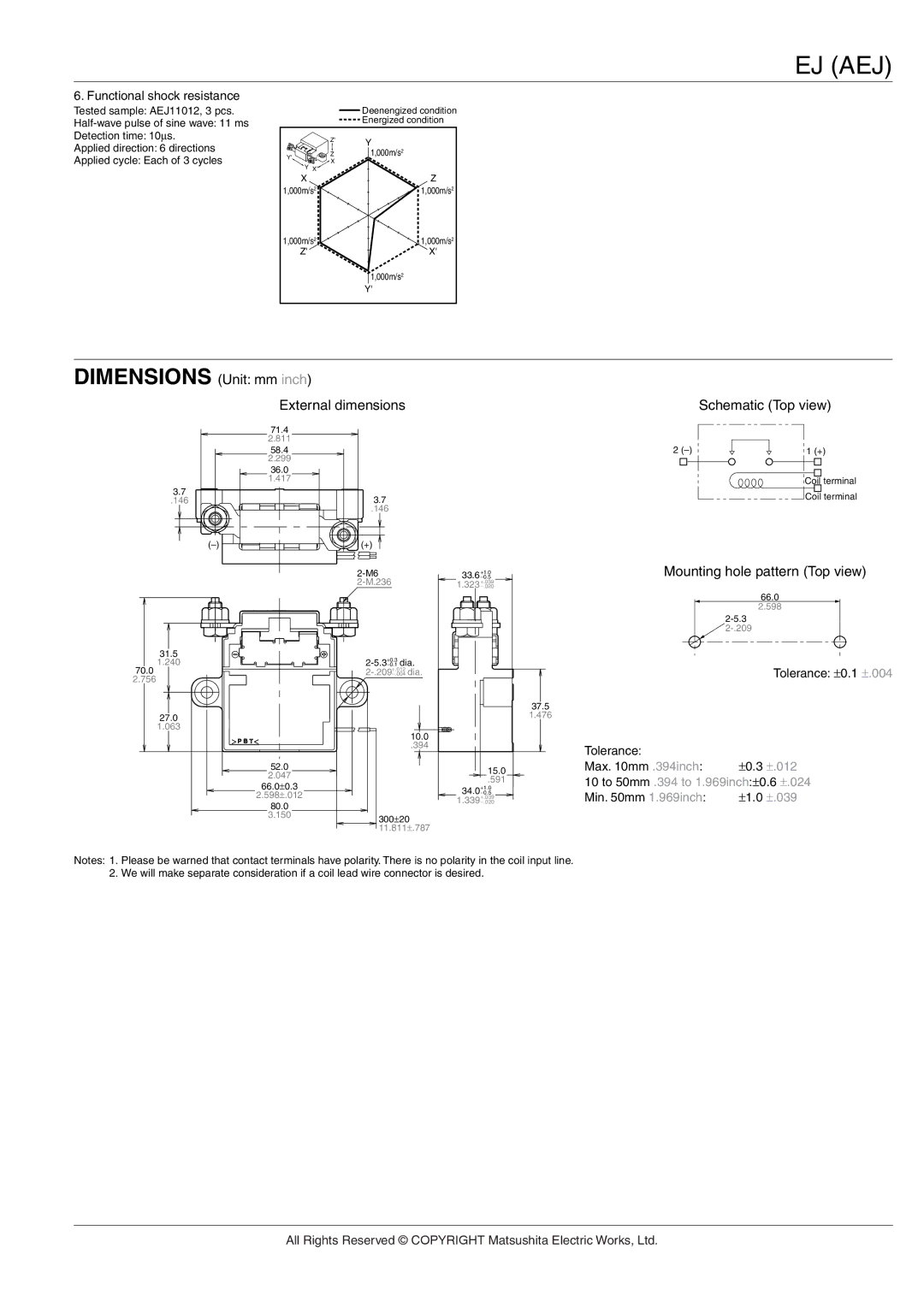
6. Functional shock resistance
Tested sample: AEJ11012, 3 pcs. |
|
| Deenengized condition |
|
| Energized condition | |
Detection time: 10∝s. |
| Z' | Y |
Applied direction: 6 directions |
|
| |
Y' | Z | 1,000m/s2 | |
Applied cycle: Each of 3 cycles | X |
| |
Y X' |
| ||
|
|
| |
| X |
| Z |
| 1,000m/s2 |
| 1,000m/s2 |
| 1,000m/s2 |
| 1,000m/s2 |
| Z' |
| X' |
|
|
| 1,000m/s2 |
|
|
| Y' |
DIMENSIONS (Unit: mm inch)
External dimensions
71.4
2.811
58.4
2.299
36.0
1.417
Schematic (Top view)
2 | 1 (+) |
Coil terminal
3.7
.146
3.7 |
.146 |
(+) |
Coil terminal
33.6 | −0.5 | Mounting hole pattern (Top view) |
| +1.0 |
|
1.323 | +.039 |
|
−.020 |
|
66.0
2.598
31.5
1.240
70.0
2.756
27.0
1.063
> ![]()
![]()
![]() <
<
52.0
2.047
66.0±0.3
2.598±.012
80.0
3.150
−0.1
−.004
10.0
.394
300±20
11.811±.787
Tolerance: ±0.1 ±.004
37.5
1.476
|
|
|
|
| Tolerance: | ±0.3 ±.012 |
|
|
|
|
| ||
|
|
|
|
| Max. 10mm .394inch: | |
|
| 15.0 |
| |||
|
|
| .591 |
| 10 to 50mm .394 to 1.969inch:±0.6 ±.024 | |
| 34.0 | +1.0 |
| |||
| −0.5 |
| Min. 50mm 1.969inch: | ±1.0 ±.039 | ||
| 1.339 | −.020 |
| |||
|
| +.039 |
|
|
| |
Notes: 1. Please be warned that contact terminals have polarity. There is no polarity in the coil input line. 2. We will make separate consideration if a coil lead wire connector is desired.
All Rights Reserved © COPYRIGHT Matsushita Electric Works, Ltd.