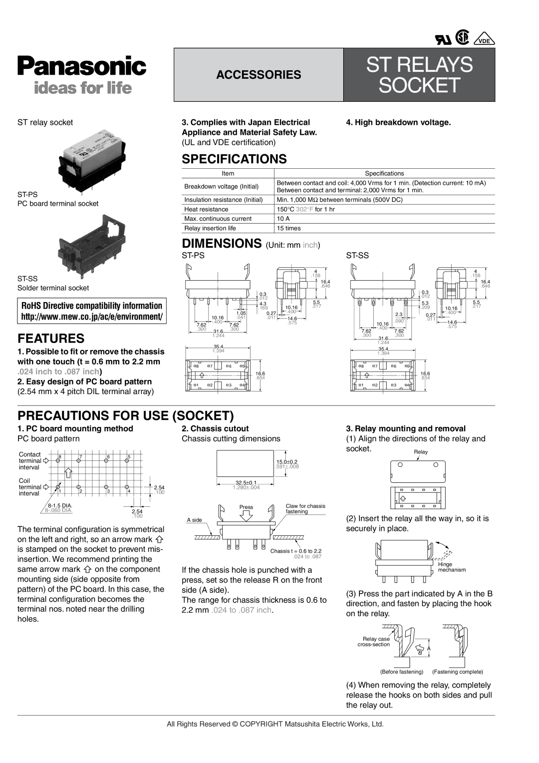
IC Drivable PC Board specifications
Panasonic has long been a leader in innovation and technology, and their IC Drivable PC Board is a testament to their commitment to developing advanced electronic solutions. This innovative product is designed to cater to a variety of applications, providing robust performance and reliable operation for industry professionals.One of the most notable features of the Panasonic IC Drivable PC Board is its flexibility in supporting multiple integrated circuits (ICs). This board can accommodate various IC types, allowing engineers and designers to create customized solutions to meet specific project requirements. Its versatility makes it an excellent choice for prototyping and production in sectors such as automotive, industrial automation, and consumer electronics.
The IC Drivable PC Board is engineered with high-quality materials that ensure durability and longevity, even in demanding environments. The board's surface finish is optimized to withstand corrosion and environmental stress, ensuring that it maintains its integrity over time. Additionally, its compact design allows for efficient space utilization within electronic devices, making it suitable for applications where board space is at a premium.
In terms of technology, the board features advanced power management capabilities, which enhance energy efficiency and reduce overall power consumption. Panasonic incorporates innovative circuit designs that minimize energy loss, resulting in a more sustainable product that meets contemporary environmental standards.
Furthermore, the IC Drivable PC Board supports various communication protocols, enabling seamless integration with other devices and systems. This feature is critical for developing interconnected solutions, which are becoming increasingly essential in today's smart technology landscape. The board's ability to interface with different communication standards facilitates easier collaboration across platforms, which is vital for successful device integration.
Reliability is another key characteristic of the Panasonic IC Drivable PC Board. The board undergoes rigorous testing to ensure that it meets the highest industry standards. This includes thermal cycling, vibration, and shock testing, which help verify its performance under challenging conditions.
In summary, the Panasonic IC Drivable PC Board represents a synthesis of versatility, durability, and advanced technology. With its ability to accommodate various ICs, robust design, energy-efficient features, and support for multiple communication protocols, it stands out as a premier choice for engineers and designers seeking a reliable solution for their electronic applications. As industries continue to evolve, Panasonic's commitment to innovation keeps its products at the forefront of technological advancements, making them an excellent partner in today's fast-paced electronic landscape.

