LDVDE(ALD) |
1 FORM A | LD RELAYS (ALD) |
SLIM POWER RELAY |
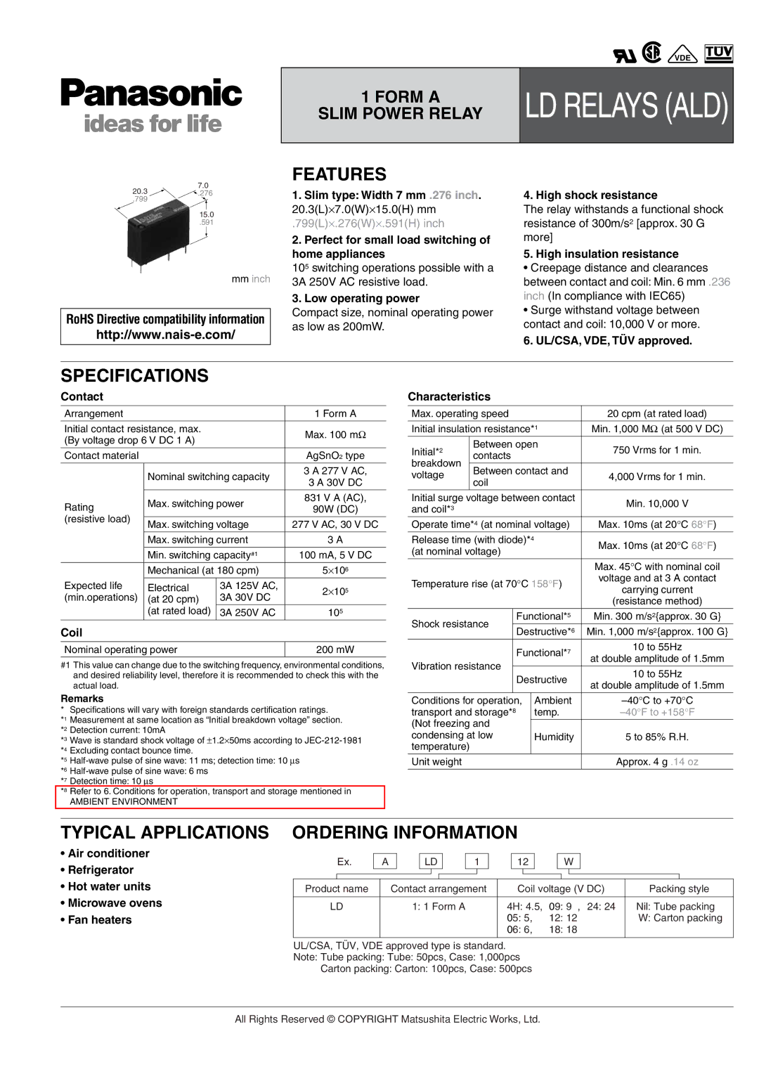
20.3 | 7.0 |
.276 | |
.799 |
|
15.0
.591
mm inch
RoHS Directive compatibility information
FEATURES
1.Slim type: Width 7 mm .276 inch. 20.3(L)×7.0(W)×15.0(H) mm
.799(L)×.276(W)×.591(H) inch
2.Perfect for small load switching of home appliances
105switching operations possible with a
3A 250V AC resistive load.
3.Low operating power
Compact size, nominal operating power as low as 200mW.
4. High shock resistance
The relay withstands a functional shock resistance of 300m/s2 [approx. 30 G more]
5. High insulation resistance
•Creepage distance and clearances between contact and coil: Min. 6 mm .236 inch (In compliance with IEC65)
•Surge withstand voltage between contact and coil: 10,000 V or more.
6. UL/CSA, VDE, TÜV approved.
SPECIFICATIONS
Contact
Arrangement |
|
| 1 Form A | |
|
|
| ||
Initial contact resistance, max. |
| Max. 100 mΩ | ||
(By voltage drop 6 V DC 1 A) |
| |||
|
| |||
Contact material |
|
| AgSnO2 type | |
| Nominal switching capacity | 3 A 277 V AC, | ||
| 3 A 30V DC | |||
|
|
| ||
Rating | Max. switching power | 831 V A (AC), | ||
90W (DC) | ||||
|
| |||
(resistive load) |
|
|
| |
Max. switching voltage | 277 V AC, 30 V DC | |||
| ||||
| Max. switching current | 3 A | ||
| Min. switching capacity#1 | 100 mA, 5 V DC | ||
| Mechanical (at 180 cpm) | 5×10⁶ | ||
Expected life | Electrical | 3A 125V AC, | 2×10⁵ | |
(min.operations) | 3A 30V DC | |||
(at 20 cpm) |
| |||
| (at rated load) | 3A 250V AC | 105 | |
Coil
Nominal operating power | 200 mW |
|
|
#1 This value can change due to the switching frequency, environmental conditions, and desired reliability level, therefore it is recommended to check this with the actual load.
Remarks
* Specifications will vary with foreign standards certification ratings.
*1 Measurement at same location as “Initial breakdown voltage” section. *2 Detection current: 10mA
*3 Wave is standard shock voltage of ±1.2×50ms according to
*5
*6
*7 Detection time: 10 µs
*8 Refer to 6. Conditions for operation, transport and storage mentioned in
AMBIENT ENVIRONMENT
Characteristics
Max. operating speed |
| 20 cpm (at rated load) | |||||
|
| ||||||
Initial insulation resistance*1 | Min. 1,000 MΩ (at 500 V DC) | ||||||
Initial*2 |
| Between open | 750 Vrms for 1 min. | ||||
| contacts |
| |||||
breakdown |
|
|
| ||||
| Between contact and |
| |||||
voltage |
| 4,000 Vrms for 1 min. | |||||
| coil |
| |||||
|
|
|
| ||||
Initial surge voltage between contact | Min. 10,000 V | ||||||
and coil*3 |
|
|
|
| |||
|
|
|
|
| |||
Operate time*4 (at nominal voltage) | Max. 10ms (at 20°C 68°F) | ||||||
Release time (with diode)*4 |
| Max. 10ms (at 20°C 68°F) | |||||
(at nominal voltage) |
| ||||||
|
| ||||||
|
|
|
|
|
| Max. 45°C with nominal coil | |
Temperature rise (at 70°C 158°F) | voltage and at 3 A contact | ||||||
carrying current | |||||||
|
|
|
|
|
| ||
|
|
|
|
|
| (resistance method) | |
Shock resistance | Functional*5 | Min. 300 m/s2{approx. 30 G} | |||||
Destructive*6 | Min. 1,000 m/s2{approx. 100 G} | ||||||
|
|
| |||||
|
|
| Functional*7 | 10 to 55Hz | |||
|
|
| at double amplitude of 1.5mm | ||||
Vibration resistance |
|
|
| ||||
Destructive | 10 to 55Hz | ||||||
|
|
| |||||
|
|
| at double amplitude of 1.5mm | ||||
|
|
|
|
|
| ||
|
|
|
|
| |||
Conditions for operation, |
| Ambient | |||||
transport and storage*8 |
| temp. | |||||
(Not freezing and |
|
|
| ||||
condensing at low |
| Humidity | 5 to 85% R.H. | ||||
temperature) |
|
|
|
|
| ||
Unit weight |
|
|
|
| Approx. 4 g .14 oz | ||
TYPICAL APPLICATIONS
•Air conditioner
•Refrigerator
•Hot water units
•Microwave ovens
•Fan heaters
ORDERING INFORMATION
|
| Ex. |
| A |
|
| LD |
| 1 |
|
| 12 |
|
|
|
| W |
|
|
|
| ||||||
|
|
|
|
|
|
|
|
|
|
|
|
|
|
|
|
|
|
|
| ||||||||
Product name |
|
| Contact arrangement |
|
| Coil voltage (V DC) | Packing style | ||||||||||||||||||||
|
|
|
|
|
|
|
|
|
|
| |||||||||||||||||
LD |
|
|
| 1: 1 Form A |
|
|
| 4H: 4.5, | 09: 9 , 24: 24 | Nil: Tube packing | |||||||||||||||||
|
|
|
|
|
|
|
|
|
|
|
|
|
|
| 05: 5, |
| 12: 12 |
| W: Carton packing | ||||||||
|
|
|
|
|
|
|
|
|
|
|
|
|
|
| 06: 6, |
| 18: 18 |
|
|
|
| ||||||
|
|
|
|
|
|
|
|
|
|
|
|
|
|
|
|
|
|
|
|
|
|
|
|
|
|
|
|
UL/CSA, TÜV, VDE approved type is standard.
Note: Tube packing: Tube: 50pcs, Case: 1,000pcs
Carton packing: Carton: 100pcs, Case: 500pcs
All Rights Reserved © COPYRIGHT Matsushita Electric Works, Ltd.