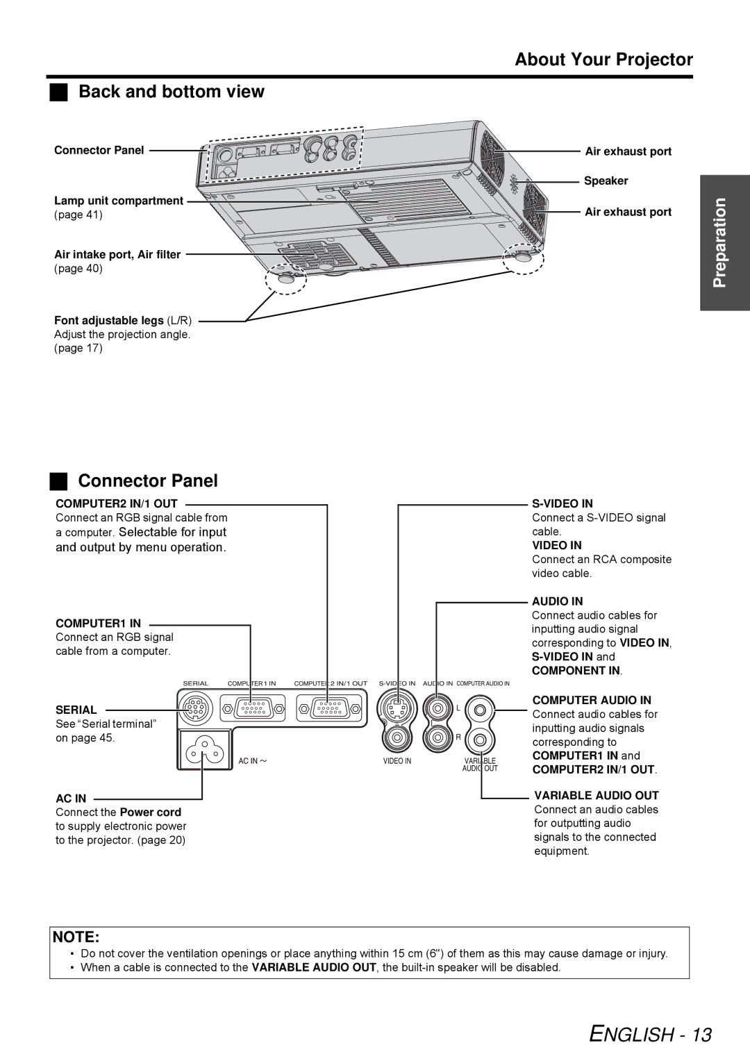
Back and bottom view
Connector Panel
Lamp unit compartment (page 41)
Air intake port, Air filter (page 40)
Font adjustable legs (L/R) Adjust the projection angle. (page 17)
Connector Panel
COMPUTER2 IN/1 OUT
Connect an RGB signal cable from a computer. Selectable for input and output by menu operation.
COMPUTER1 IN Connect an RGB signal cable from a computer.
SERIAL
See “Serial terminal” on page 45.
AC IN
Connect the Power cord to supply electronic power to the projector. (page 20)
About Your Projector
Air exhaust port |
| |
Speaker |
| |
Preparation | ||
Air exhaust port | ||
| ||
|
|
Connect a
VIDEO IN
Connect an RCA composite video cable.
AUDIO IN
Connect audio cables for inputting audio signal corresponding to VIDEO IN,
COMPONENT IN.
COMPUTER AUDIO IN Connect audio cables for inputting audio signals corresponding to COMPUTER1 IN and
COMPUTER2 IN/1 OUT.
VARIABLE AUDIO OUT Connect an audio cables for outputting audio signals to the connected equipment.
NOTE:
•Do not cover the ventilation openings or place anything within 15 cm (6") of them as this may cause damage or injury.
•When a cable is connected to the VARIABLE AUDIO OUT, the
