Connections
SERIAL Terminals connection
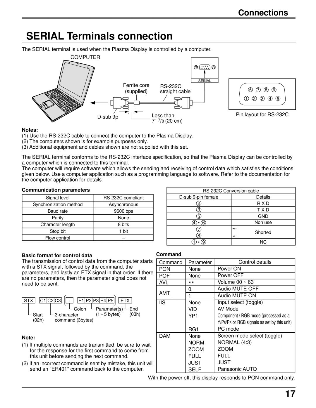
The SERIAL terminal is used when the Plasma Display is controlled by a computer.
COMPUTER
SERIAL
Ferrite core | |
(supplied) | straight cable |
Less than | |
| 7" 7/8 (20 cm) |
Notes:
(1)Use the
(2)The computers shown is for example purposes only.
(3)Additional equipment and cables shown are not supplied with this set.
6 7 8 9
1 2 3 4 5
Pin layout for
The SERIAL terminal conforms to the
The computer will require software which allows the sending and receiving of control data which satisfies the conditions given below. Use a computer application such as a programming language to software. Refer to the documentation for the computer application for details.
Communication parameters
Signal level | |
|
|
Synchronization method | Asynchronous |
Baud rate | 9600 bps |
|
|
Parity | None |
|
|
Character length | 8 bits |
Stop bit | 1 bit |
|
|
Flow control | – |
Details | |||
| 2 |
| R X D |
| 3 |
| T X D |
| 5 |
| GND |
4 | • | 6 | Non use |
| 7 |
| Shorted |
| 8 |
| |
|
|
| |
1 | • | 9 | NC |
Basic format for control data |
|
|
|
|
|
|
|
|
| Command |
|
| ||||||||||||||||
The transmission of control data from the computer starts | Command | Parameter | Control details | |||||||||||||||||||||||||
with a STX signal, followed by the command, the |
|
|
| |||||||||||||||||||||||||
PON | None | Power ON | ||||||||||||||||||||||||||
parameters, and lastly an ETX signal in that order. If there | ||||||||||||||||||||||||||||
POF | None | Power OFF | ||||||||||||||||||||||||||
are no parameters, then the parameter signal does not | ||||||||||||||||||||||||||||
AVL | ** | Volume 00 ~ 63 | ||||||||||||||||||||||||||
need to be sent. |
|
|
|
|
|
|
|
|
| |||||||||||||||||||
|
|
|
|
|
|
|
|
|
| Audio MUTE OFF | ||||||||||||||||||
|
|
|
|
|
|
|
|
|
|
|
|
|
|
|
|
|
|
|
|
|
|
|
|
| AMT | 0 | ||
|
|
|
|
|
|
|
|
|
|
|
|
|
|
|
|
|
|
|
|
|
|
|
|
| 1 | Audio MUTE ON | ||
|
|
|
|
|
|
|
|
|
|
|
|
|
|
|
|
|
|
|
|
|
|
|
|
|
| |||
STX |
| C1 | C2 | C3 |
| : |
|
| P1 | P2 | P3 | P4 | P5 |
| ETX |
|
|
|
| |||||||||
IIS | None | Input select (toggle) | ||||||||||||||||||||||||||
|
|
|
|
|
|
|
|
|
|
|
|
|
|
|
|
|
|
|
|
|
|
|
|
| ||||
|
|
|
|
|
|
|
|
|
|
| Colon |
| Parameter(s) |
|
| End |
| VID | AV Mode | |||||||||
|
|
|
|
|
|
|
|
|
|
|
|
|
| |||||||||||||||
Start |
|
|
| (1 - 5 bytes) | (03h) |
| YP1 | Component / RGB mode (processed as a | ||||||||||||||||||||
|
|
|
| |||||||||||||||||||||||||
(02h) |
|
|
| command (3bytes) |
|
|
|
|
|
|
|
|
|
|
| Y/PB/PR or RGB signals as set by this unit) | ||||||||||||
|
|
|
|
|
|
|
|
|
|
|
|
|
|
|
|
|
|
|
|
|
|
|
|
|
|
| ||
|
|
|
|
|
|
|
|
|
|
|
|
|
|
|
|
|
|
|
|
|
|
|
|
|
| RG1 | PC mode | |
Note: |
|
|
|
|
|
|
|
|
|
|
|
|
|
|
|
|
|
|
|
|
|
| DAM | None | Screen mode select (toggle) | |||
|
|
|
|
|
|
|
|
|
|
|
|
|
|
|
|
|
|
|
|
|
|
| NORM | NORMAL (4:3) | ||||
(1) If multiple commands are transmitted, be sure to wait |
| |||||||||||||||||||||||||||
| ZOOM | ZOOM | ||||||||||||||||||||||||||
for the response for the first command to come from |
| |||||||||||||||||||||||||||
this unit before sending the next command. |
|
|
| FULL | FULL | |||||||||||||||||||||||
(2) If an incorrect command is sent by mistake, this unit will |
| JUST | JUST | |||||||||||||||||||||||||
send an “ER401” command back to the computer. |
| SELF | Panasonic AUTO | |||||||||||||||||||||||||
With the power off, this display responds to PON command only.
17