Installation and Operation Guide
Door Station
Model No. VL-V566BX
Thank you for purchasing a Panasonic product.
LPlease read this guide before using the unit and save for future reference.
LPlease read this guide carefully, and install the unit safely and correctly by following the instructions. Panasonic assumes no responsibility for injuries or property damage resulting from failures arising out of improper installation or operation inconsistent with this guide.
For your safety
To prevent severe injury and loss of life/property, read this section carefully before using the unit to ensure proper and safe operation of your unit.
WARNING
LTo reduce the risk of electric shock, do not disassemble this unit. Refer servicing to an authorized service center when service is required. Opening or removing covers may expose you to dangerous voltages or other risks. Incorrect reassembly can cause electric shock when the unit is subsequently used.
LNever install wiring during a lightning storm.
LWhen existing chime wires are used, it is possible that they contain AC voltage. Electric shock or unit damage could result. Contact an authorized service center.
CAUTION
LInstall the unit securely adhering to the instructions in this guide to prevent it from falling off the wall. Avoid installing onto
LIf the wiring is underground, do not make any connections underground. LIf the wiring is underground, use a protection tube.
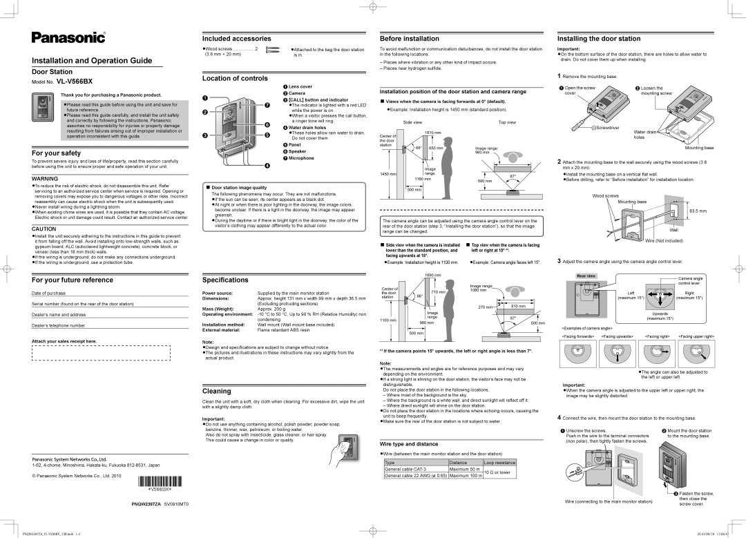
Included accessories
LWood screws ..................2 | LAttached to the bag the door station |
(3.8 mm × 20 mm) | is in. |
Location of controls
|
| A Lens cover | |
A |
| B Camera | |
| C {CALL} button and indicator | ||
|
| ||
| G | LThe indicator is lighted with a red LED | |
B |
| while the power is on. | |
| LWhen a visitor presses the call button, | ||
|
| ||
| F | a ringer tone will ring. | |
| D Water drain holes | ||
|
| ||
C | E | LThese holes allow rain water to drain. | |
Do not cover them. | |||
|
| ||
|
| E Panel | |
|
| F Speaker | |
|
| G Microphone |
D
N Door station image quality
The following phenomena may occur. They are not malfunctions. LIf the sun can be seen, its center appears as a black dot.
LAt night or when there is poor lighting in the doorway, the image colors become unclear. If there is a light in the doorway, the image may appear greenish.
LDuring the daytime or if there is bright light in the doorway, the color of the visitor’s clothing may appear differently to the actual color.
Before installation
To avoid malfunction or communication disturbances, do not install the door station in the following locations:
–Places where vibration or any other kind of impact occurs.
–Places near hydrogen sulfide.
Installation position of the door station and camera range
N Views when the camera is facing forwards at 0° (default).
LExample: Installation height is 1450 mm (standard position).
|
|
| Side view | Top view | ||||||||
|
|
|
|
|
| 1810 mm |
| |||||
Center of |
| |||||||||||
|
|
|
|
|
|
| ||||||
the door |
|
|
|
|
|
|
| |||||
station |
|
|
|
|
|
|
|
| ||||
|
| 650 | mm | Image range: | ||||||||
|
|
|
|
| 66° |
|
| |||||
|
|
|
|
|
|
|
|
|
|
|
| 960 mm |
|
|
|
|
|
|
|
|
|
|
|
| |
|
|
|
|
|
|
|
|
|
|
|
|
|
|
|
|
|
|
|
|
|
|
|
|
|
|
| Image |
|
1450 mm | range | 87° |
| 1160 mm | |
| 500 mm | |
|
| |
| 500 mm |
|
The camera angle can be adjusted using the camera angle control lever on the rear of the door station (step 3, “Installing the door station”), so that the image range can be changed.
N Side view when the camera is installed | N Top view when the camera is facing |
lower than the standard position, and | left or right at 15° *1. |
facing upwards at 15°. |
|
LExample: Installation height is 1100 mm. | LExample: Camera angle faces left 15°. |
Installing the door station
Important:
LOn the bottom surface of the door station, there are holes to allow water to drain. Do not cover them up when installing.
1 Remove the mounting base. |
|
A Open the screw | B Loosen the |
cover. | mounting screw. |
![]()
![]() TScrewdriver
TScrewdriver
Water drain holes
Mounting base
2 Attach the mounting base to the wall securely using the wood screws (3.8 mm x 20 mm).
LInstall the mounting base on a vertical flat wall.
LBefore drilling, refer to “Before installation” for installation location.
Wood screws
Mounting base
83.5 mm
Wall
Wire (Not included)
3 Adjust the camera angle using the camera angle control lever.
For your future reference
Date of purchase
Serial number (found on the rear of the door station)
Dealer’s name and address
Dealer’s telephone number
Specifications
Power source: | Supplied by the main monitor station |
Dimensions: | Approx. height 131 mm x width 99 mm x depth 36.5 mm |
| (Excluding protruding sections) |
Mass (Weight): | Approx. 200 g |
Operating environment: | |
| condensing |
Installation method: | Wall mount (Wall mount base included) |
External material: | Flame retardant ABS resin |
|
|
|
|
|
| 1690 mm |
| |||
Center of |
|
|
|
|
|
|
|
| Image range: | |
|
|
|
|
|
|
|
| |||
|
|
|
|
| 710 | mm | 1080 mm | |||
the door |
|
| 66° |
| ||||||
station |
|
|
|
|
|
| ||||
|
|
|
|
| ||||||
|
|
|
|
|
|
|
|
|
|
|
| 270 mm | 810 mm | |
| Image |
| |
1100 mm | range | 87° | |
980 mm | 500 mm | ||
| |||
| 500 mm |
|
Rear view
Left
(maximum 15°)
Upwards
(maximum 15°)
<Examples of camera angle>
Camera angle control lever
Right
(maximum 15°)
Attach your sales receipt here.
© Panasonic System Networks Co., Ltd. 2010
PNQW2397ZA SV0910MT0
Note:
LDesign and specifications are subject to change without notice.
LThe pictures and illustrations in these instructions may vary slightly from the actual product.
Cleaning
Clean the unit with a soft, dry cloth when cleaning. For excessive dirt, wipe the unit with a slightly damp cloth.
Important:
LDo not use anything containing alcohol, polish powder, powder soap, benzine, thinner, wax, petroleum, or boiling water.
Also do not spray with insecticide, glass cleaner, or hair spray. This could cause a change in color or quality.
*1 If the camera points 15° upwards, the left or right angle is less than 7°.
Note:
LThe measurements and angles are for reference purposes and may vary depending on the environment.
LIf a strong light is shining on the door station, the visitor’s face may not be distinguishable.
Do not place the door station in the following locations.
–Where most of the background is the sky.
–Where the background is a white wall, and direct sunlight will reflect off it.
–Where direct sunlight will shine on the door station.
LDo not place the door station in the locations where echoing occurs, causing the unit to beep frequently.
LMake sure the rear of the door station is not subject to water.
Wire type and distance
LWire (between the main monitor station and the door station):
Type | Distance | Loop resistance |
General cable | Maximum 50 m | 10 Ω or lower |
General cable 22 AWG (ø 0.65) | Maximum 100 m |
<Facing forwards> |
| <Facing upwards> |
| <Facing right> |
| <Facing upper right> |
|
|
|
|
|
|
|
|
|
|
|
|
|
|
LThe angle can also be adjusted to the left or upper left.
Important:
LWhen the camera angle is adjusted to the upper left or upper right, the image may be slightly distorted.
4 Connect the wire, then mount the door station to the mounting base.
A Unscrew the screws. | B Mount the door station |
Push in the wire to the terminal connectors | to the mounting base. |
(non polar), then tightly fasten the screws. |
|
| C Fasten the screw, | |
Wire (connecting to the main monitor station) | then close the | |
screw cover. | ||
|
2010/08/19 | 17:06:47 |
|
|
|
|
|
| ||
|
|
| ||
|
|
|
|
|