■General
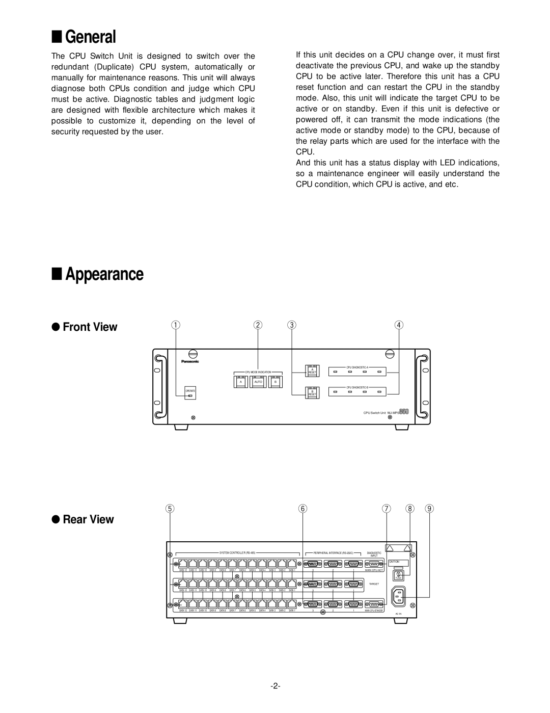
The CPU Switch Unit is designed to switch over the redundant (Duplicate) CPU system, automatically or manually for maintenance reasons. This unit will always diagnose both CPUs condition and judge which CPU must be active. Diagnostic tables and judgment logic are designed with flexible architecture which makes it possible to customize it, depending on the level of security requested by the user.
If this unit decides on a CPU change over, it must first deactivate the previous CPU, and wake up the standby CPU to be active later. Therefore this unit has a CPU reset function and can restart the CPU in the standby mode. Also, this unit will indicate the target CPU to be active or on standby. Even if this unit is defective or powered off, it can transmit the mode indications (the active mode or standby mode) to the CPU, because of the relay parts which are used for the interface with the CPU.
And this unit has a status display with LED indications, so a maintenance engineer will easily understand the CPU condition, which CPU is active, and etc.
■Appearance
●Front View
q
OPERATE
| w | e | r |
|
|
| CPU |
| CPU MODE INDICATION |
| A |
|
| RESET | |
A | AUTO | B |
|
|
|
| CPU |
|
|
| B |
|
|
| RESET |
|
|
| CPU Switch Unit |
●Rear View
t
SYSTEM CONTROLLER
|
|
|
|
|
|
|
|
|
|
|
|
|
|
|
|
|
|
|
|
|
|
|
|
|
|
|
|
|
|
|
|
|
|
|
|
|
|
|
|
|
|
|
|
|
|
|
|
|
|
|
|
|
|
| DATA 12 | DATA 11 | DATA 10 | DATA 9 | DATA 8 | DATA 7 | DATA 6 | DATA 5 | DATA 4 | DATA 3 | DATA 2 | DATA 1 | ||||||||||||||
|
|
|
|
|
|
|
|
|
|
|
|
|
|
|
|
|
|
|
|
|
|
|
|
|
|
|
|
|
|
|
|
|
|
|
|
|
|
|
|
|
|
|
|
|
|
|
|
|
|
|
|
|
|
|
|
|
|
|
|
|
|
|
|
|
|
|
|
|
|
|
|
|
|
|
|
|
|
| ||
|
|
|
|
|
|
|
|
|
|
|
|
|
|
|
|
|
|
|
|
|
|
|
|
|
|
|
| DATA 12 | DATA 11 | DATA 10 | DATA 9 | DATA 8 | DATA 7 | DATA 6 | DATA 5 | DATA 4 | DATA 3 | DATA 2 | DATA 1 | ||||||||||||||
y |
|
|
| PERIPHERAL INTERFACE | |
3 | 2 | 1 |
3 | 2 | 1 |
3 | 2 | 1 |
u | i | o |
DIAGNOSTIC |
|
|
INPUT |
|
|
CAITION |
|
|
MAIN |
|
|
PUSH |
|
|
FUSE |
|
|
TARGET |
|
|
MAIN
AC IN
