qOperate Indicator (OPERATE)
Is on when the power of the
Note: The power switch of the CPU Switch Unit is located underneath the front panel.
Remove the front panel by removing four screws on the panel.
wCPU Mode Selector (A / AUTO / B)
LEDs in the buttons indicate the selected mode of the CPU Switch Unit.
• A and B Buttons
On: Indicates the active mode is selected.
Off: Indicates the standby mode is selected.
• AUTO Button
On: Indicates the auto switching mode is select- ed.
Off: Indicates the manual switching mode is selected.
eReset Buttons (A RESET, B RESET)
Press these buttons when the CPUs reject control from the external unit.
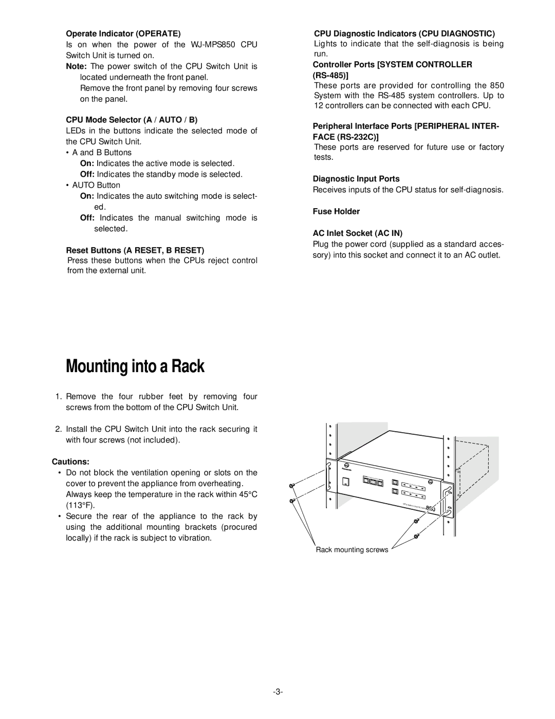
■Mounting into a Rack
1.Remove the four rubber feet by removing four screws from the bottom of the CPU Switch Unit.
2.Install the CPU Switch Unit into the rack securing it with four screws (not included).
Cautions:
•Do not block the ventilation opening or slots on the cover to prevent the appliance from overheating. Always keep the temperature in the rack within 45°C (113°F).
•Secure the rear of the appliance to the rack by using the additional mounting brackets (procured locally) if the rack is subject to vibration.
rCPU Diagnostic Indicators (CPU DIAGNOSTIC) Lights to indicate that the
tController Ports [SYSTEM CONTROLLER
These ports are provided for controlling the 850 System with the
yPeripheral Interface Ports [PERIPHERAL INTER- FACE
These ports are reserved for future use or factory tests.
uDiagnostic Input Ports
Receives inputs of the CPU status for
iFuse Holder
oAC Inlet Socket (AC IN)
Plug the power cord (supplied as a standard acces- sory) into this socket and connect it to an AC outlet.
CPU MODE |
|
|
INDICATION |
|
|
A |
|
|
AUTO | A |
|
B | RESET | CPU |
|
|
B |
|
RESET | CPU |
|
CPU |
|
|
Switch |
| 850 |
Unit |
Rack mounting screws