7.Do not operate the camera beyond the specified temperature, humidity or power source ratings.
Use the camera under conditions where tem- perature is between
Caution:
To prevent fire or electric shock hazard, use a UL listed cable
MAJOR OPERATING CONTROLS AND THEIR FUNCTIONS
BLC ON
(ELC)(ALC)
VIDEO![]()
![]() ALC
ALC
VIDEO OUT | DC |
| ELC | |
| ||||
|
| OFF | ||
|
|
|
|
|
|
|
|
|
|
| AC 24V IN | |
|
| GND |
| 1 | 2 |
| BLC ON | |
| (ELC)(ALC) | |
| VIDEO | ALC |
VIDEO OUT | DC | ELC |
|
| OFF |
DC 12V IN
BLC ON
(ELC)(ALC)
VIDEO![]()
![]() ALC
ALC
VIDEO OUT | DC |
| ELC | |
| ||||
|
| OFF | ||
|
|
|
|
|
|
|
|
|
|
|
| LOCK |
|
BLC ON |
|
| |
(ELC)(ALC) | WV– BP144 |
| |
VIDEO | ALC |
|
|
DC | ELC |
|
|
OFF |
|
|
|
|
| Camera Mounting | Fixing Screws |
|
| Screw Holes |
|
![]()
![]() Mount Adapter
Mount Adapter
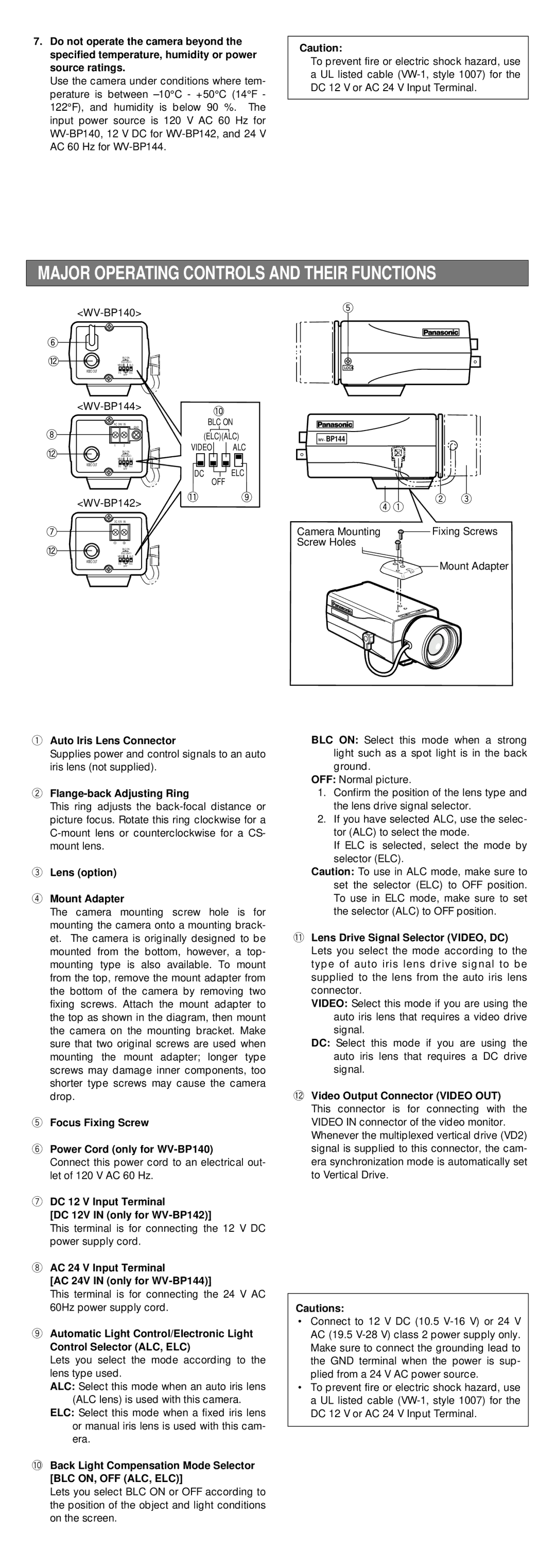
qAuto Iris Lens Connector
Supplies power and control signals to an auto iris lens (not supplied).
wFlange-back Adjusting Ring
This ring adjusts the
eLens (option)
rMount Adapter
The camera mounting screw hole is for mounting the camera onto a mounting brack- et. The camera is originally designed to be mounted from the bottom, however, a top- mounting type is also available. To mount from the top, remove the mount adapter from the bottom of the camera by removing two fixing screws. Attach the mount adapter to the top as shown in the diagram, then mount the camera on the mounting bracket. Make sure that two original screws are used when mounting the mount adapter; longer type screws may damage inner components, too shorter type screws may cause the camera drop.
tFocus Fixing Screw
yPower Cord (only for
Connect this power cord to an electrical out- let of 120 V AC 60 Hz.
uDC 12 V Input Terminal
[DC 12V IN (only for
This terminal is for connecting the 12 V DC power supply cord.
iAC 24 V Input Terminal
[AC 24V IN (only for
This terminal is for connecting the 24 V AC 60Hz power supply cord.
oAutomatic Light Control/Electronic Light Control Selector (ALC, ELC)
Lets you select the mode according to the lens type used.
ALC: Select this mode when an auto iris lens (ALC lens) is used with this camera.
ELC: Select this mode when a fixed iris lens or manual iris lens is used with this cam- era.
!0Back Light Compensation Mode Selector [BLC ON, OFF (ALC, ELC)]
Lets you select BLC ON or OFF according to the position of the object and light conditions on the screen.
BLC ON: Select this mode when a strong light such as a spot light is in the back ground.
OFF: Normal picture.
1.Confirm the position of the lens type and the lens drive signal selector.
2.If you have selected ALC, use the selec- tor (ALC) to select the mode.
If ELC is selected, select the mode by selector (ELC).
Caution: To use in ALC mode, make sure to set the selector (ELC) to OFF position. To use in ELC mode, make sure to set the selector (ALC) to OFF position.
!1Lens Drive Signal Selector (VIDEO, DC)
Lets you select the mode according to the type of auto iris lens drive signal to be supplied to the lens from the auto iris lens connector.
VIDEO: Select this mode if you are using the auto iris lens that requires a video drive signal.
DC: Select this mode if you are using the auto iris lens that requires a DC drive signal.
!2Video Output Connector (VIDEO OUT)
This connector is for connecting with the VIDEO IN connector of the video monitor. Whenever the multiplexed vertical drive (VD2) signal is supplied to this connector, the cam- era synchronization mode is automatically set to Vertical Drive.
Cautions:
•Connect to 12 V DC (10.5
•To prevent fire or electric shock hazard, use a UL listed cable