■Mounting the Camera
Disassembly of the camera
IMAGE ADJUSTMENT
1. Remove the panel cover with a Phillips screwdriver.
2. Turn the panel cover
3. Remove the panel cover. | 4. Remove the inner dome. |
To mount the camera on a junction box | To mount the camera directly on the | ||
1. | Install the junction box on the wall/ceiling. | wall/ceiling | |
2. | Attach the four screws to the junction box. | 1. | Prepare the mounting space. |
3. | Hook the camera to the four screws, and | 2. | Place the camera on the wall/ceiling and |
| turn it clockwise. |
| mark four screw positions with a pen. |
4. | Fasten all the mounting screws. | 3. | Attach the four screws (not supplied) to the |
|
|
| wall/ceiling. |
|
| 4. | Hook the camera to the four screws, and |
|
|
| turn it clockwise. |
|
| 5. | Fasten all the mounting screws. |
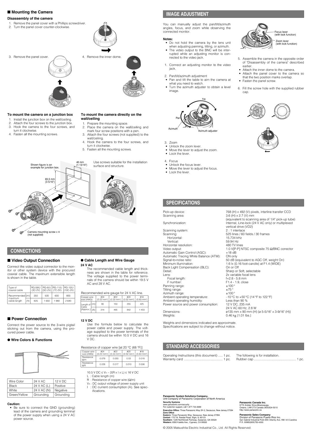
You can manually adjust the pan/tilt/azimuth angles, focus, and zoom while observing the connected monitor.
Notes:
•Do not hold the camera by the lens unit when adjusting panning, tilting, or azimuth.
•The video output to the BNC will be inter- rupted while an adjusting monitor is con- nected to the video jack.
1.Connect an adjusting monitor to the video jack.
2.Pan/tilt/azimuth adjustment
•Pan and tilt the table to aim the camera at what you need to watch.
•Turn the azimuth adjuster to obtain a level image.
Tilt
Pan
Azimuth
Azimuth adjuster
3. Zoom
•Unlock the zoom lever.
•Move the lever to adjust the zoom.
•Lock the lever.
![]()
![]()
![]() Focus lever
Focus lever ![]() (with lock function)
(with lock function)
Zoom lever
(with lock function)
5.Assemble the camera in the opposite order of "Disassembly of the camera" described earlier.
•Attach the inner dome to the camera.
•Attach the panel cover to the camera so that the two position marks overlap.
•Fasten the panel screw.
6.Fill the screw hole with the supplied rubber cap.
Shown figure is an example for junction box.
83,5 mm
Camera mounting screw x 4 (not supplied)
46 mm | Use screws suitable for the installation |
surface and structure. |
4. Focus
•Unlock the focus lever.
•Move the lever to adjust the focus.
•Lock the lever.
SPECIFICATIONS
768 (H) x 492 (V) pixels, interline transfer CCD | |
Scanning area: | 3.6 (H) x 2.7 (V) mm |
| (equivalent to scanning area of 1/4" |
Synchronization: | Internal, |
| vertical drive (VD2) |
Scanning system: | 2 : 1 interlace |
Scanning: | 525 lines / 60 fields / 30 frames |
Horizontal: | 15.734 kHz |
Vertical: | 59.94 Hz |
Horizontal resolution: | 480 TV lines |
Video output: | 1.0 |
CONNECTIONS
Automatic Gain Control (AGC): | +18 dB |
Automatic Tracing White Balance (ATW): | ON only |
■Video Output Connection
Connect the video output connector to the mon- itor or other system device with the procured coaxial cable. The maximum extensible length is shown in the table.
Type of |
| ||||
coaxial cable |
| ||||
|
|
|
|
|
|
Recommended | (m) | 250 | 500 | 600 | 800 |
maximum |
|
|
|
|
|
|
|
|
|
| |
cable length | (ft) | 825 | 1 650 | 1 980 | 2 640 |
|
|
|
|
|
|
●Cable Length and Wire Gauge
24 V AC
The recommended cable length and thick- ness are shown in the table for reference. The voltage supplied to the power termi- nals of the camera should be within 19.5 V AC and 28 V AC.
Recommended wire gauge for 24 V AC line.
Copper wire | #24 | #22 | #20 | #18 | |
size (AWG) | (0.22 mm2) | (0.33 mm2) | (0.52 mm2) | (0.83 mm2) | |
|
|
|
|
|
|
Length of | (m) | 95 | 150 | 255 | 425 |
Cable |
|
|
|
|
|
|
|
|
|
| |
(Approx.) | (ft) | 314 | 495 | 842 | 1 403 |
|
|
|
|
|
|
50 dB (equivalent to AGC Off, weight On) | |
Minimum illumination: | 1.6 lx {0.16 |
Back Light Compensation (BLC): | On or Off |
Detail: | Sharp or Soft, selectable |
Lens: | 2x variable focal lens |
Focal length: | f=2.8 - 5.8 mm |
F number: | F1.4 - 1.9, close |
Panning range: | ±100 ° |
Tilting range: | ±75 ° |
Azimuth range: | ±100 ° |
Ambient operating temperature: | |
Ambient operating humidity: | Less than 90 % |
Power source and power consumption: | 12 V DC, 235 mA |
| 24 V AC 60 Hz, 2.8 W |
Dimensions: | ø135 mm x 90 mm (H) {ø |
Weights: | 0.46 kg {1.01 lbs.} |
■Power Connection
Connect the power source to the
●Wire Colors & Functions
Wire Color | 24 V AC | 12 V DC | |
Black | 24 | V AC (L) | Positive |
White | 24 | V AC (N) | Negative |
Green/Yellow | Grounding | Grounding | |
|
|
|
|
Caution:
•Be sure to connect the GND (grounding) lead of the camera and grounding terminal of the power supply when using a 24 V AC power source.
12 V DC
Use the formula below to calculate the power cable and power supply. The volt- age supplied to the power terminals of the camera should be within 10.5 V DC and 16 V DC.
Resistance of copper wire [at 20 °C {68 °F}]
Copper wire | #24 | #22 | #20 | #18 | |
size (AWG) | (0.22 mm2) | (0.33 mm2) | (0.52 mm2) | (0.83 mm2) | |
|
|
|
|
| |
Resistance | 0.078 | 0.050 | 0.03 | 0.018 | |
Ω/m | |||||
|
|
|
| ||
|
|
|
|
| |
Resistance | 0.026 | 0.017 | 0.010 | 0.006 | |
Ω/ft | |||||
|
|
|
| ||
|
|
|
|
|
10.5V DC ≤ VA − 2(R x I x L) ≤ 16 V DC
L : Cable length (m)
R : Resistance of copper wire (Ω/m)
VA : DC output voltage of power supply unit
I : DC current consumption (A). See spec- ifications.
Weights and dimensions indicated are approximate.
Specifications are subject to change without notice.
STANDARD ACCESSORIES
Operating Instructions (this document) | 1 pc. | The following is for installation. |
|
Warranty card | 1 pc. | Rubber cap | 1 pc. |
Panasonic System Solutions Company,
Unit Company of Panasonic Corporation of North America
Security Systems | Panasonic Canada Inc. |
www.panasonic.com/security | 5770 Ambler Drive,Mississauga, |
For customer support, call 1.877.733.3689 | Ontario, L4W 2T3 Canada |
Executive Office: Three Panasonic Way | http://www.panasonic.ca |
Zone Office | Panasonic Sales Company |
Eastern: Three Panasonic Way, Secaucus, New Jersey 07094 | |
Central: 1707 N. Randal Road, Elgin, IL 60123 | Division of Panasonic Puerto Rico Inc. |
Southern: 1225 Northbrook Parkway, Suwanee, GA 30024 | San Gabriel Industrial Park 65th Infantry Ave. KM. 9.5 Carolina |
Western: 6550 Katella Ave., Cypress, CA 90630 | P.R. |
© 2005 Matsushita Electric Industrial Co., Ltd. All Rights Reserved.