7 |
SPRING PIN |
2 |
FIGURE 4 |
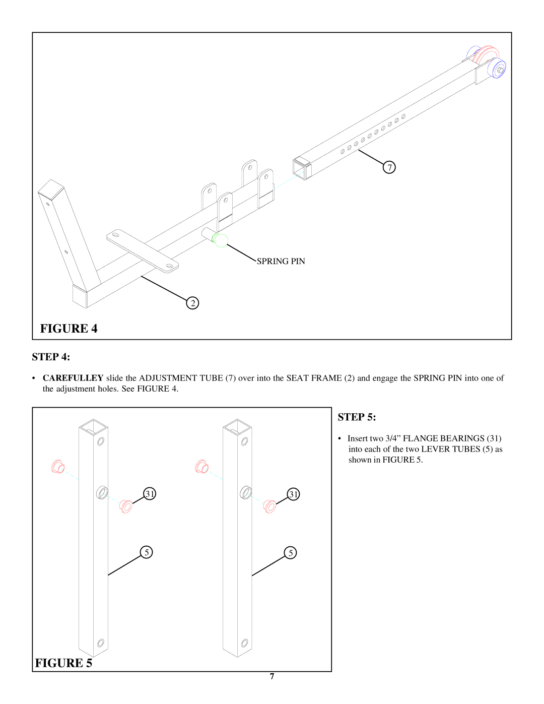
STEP 4:
•CAREFULLEY slide the ADJUSTMENT TUBE (7) over into the SEAT FRAME (2) and engage the SPRING PIN into one of the adjustment holes. See FIGURE 4.
STEP 5:
• Insert two 3/4” FLANGE BEARINGS (31) into each of the two LEVER TUBES (5) as shown in FIGURE 5.
31 | 31 |
5 | 5 |
FIGURE 5
7