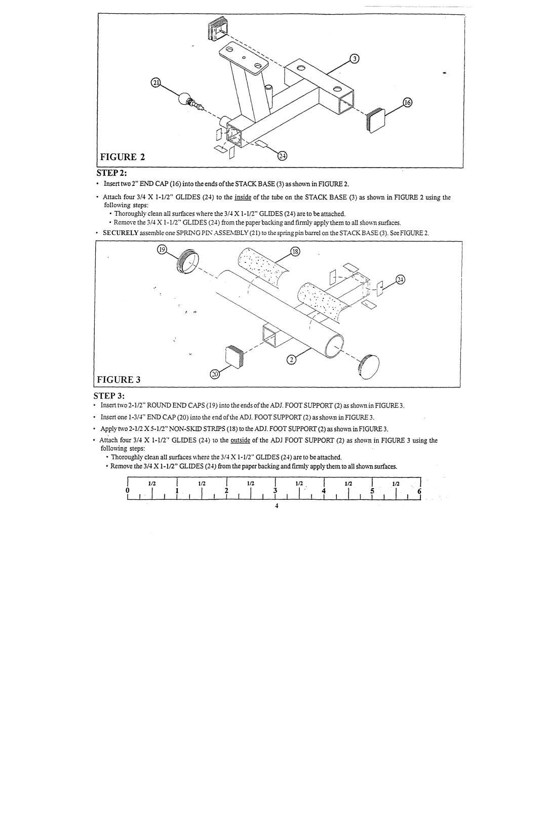
FIGURE 2
STEP2:
¯Insert two 2" ENDCAP(16) into the ends of the STACKBASE(3) as shownin FIGURE
¯Attach fou~ 3/4 X 1-1/2" GLIDES(24) to the inside of the tube on the STACKBASE(3) as shown in FIGURE2 using the following steps:
¯Thoroughlyclean all surfaces wherethe 3/4 X1-1/2" GLIDES(24) are to be attached.
¯Removethe 3/4 X1-1/2" GLIDES(24) from the paper backing and firefly apply them to all shownsurfaces.
SECURELYassemble one SPRh-NGPLY"ASSEN~LY(21) to the spring pkn barrel on the STACKBASE(3). See FIGUP~
FIGURE 3
STEP3:
¯Insert two 2-1/2" ROUNDENDCAPS(19) into the ends of the ADJ. FOOTSUPPORT(2) as shownin FIGURE
¯Insert one 1-3/4" ENDCAP(20) into the end of the ADJ.FOOTSUPPORT(2) as sho~:n in FIGURE
¯Apply m'o 2-1/2 X 5-1/2" NON-SKIDSTR.~S(18) to the ADJ. FOOTSUPPORT(2) as shown in FIGURE
¯Attach four 3/4 X 1-1/2"' GLIDES(24) so the outside of the ADJFOOTSUPPORT(2) as shoss~ in FIGURE3 using the follo~s4ngsteps:
¯Thorou~lyclean all surfaces wherethe 3/4 X1-I/2" GLIDES(24) are to be attached.
¯Removethe 3/4 X1-1/2" GLIDES(24) from the paper backing and firmly apply them to all sho~ surfaces.
] | ,/2 | 1' | l~z | [ | ~/'z | I | ~/~. | [ | l~z | [ | | .I/2 .... |
0 | | | 1. | | 2 | | | 3 | [' | 4 | 5 | 6 |
| | | | | | | | 4 | | | | |