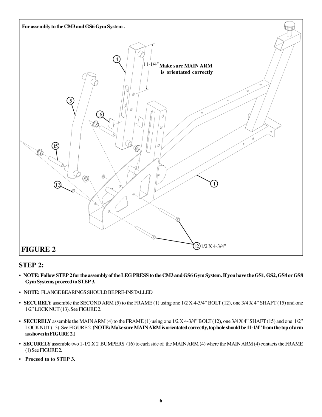
For assembly to the CM3 and GS6 Gym System .
4
11−1/4" Make sure MAIN ARM is orientated correctly
5
16
15
13 | 1 |
FIGURE 2 | 12 1/2 X |
|
STEP 2:
•NOTE: Follow STEP 2 for the assembly of the LEG PRESS to the CM3 and GS6 Gym System. If you have the GS1, GS2, GS4 or GS8 Gym Systems proceed to STEP 3.
•NOTE: FLANGE BEARINGS SHOULD BE
•SECURELY assemble the SECOND ARM (5) to the FRAME (1) using one 1/2 X
•SECURELY assemble the MAIN ARM (4) to the FRAME (1) using one 1/2 X
•SECURELY assemble two
(1) See FIGURE 2.
•Proceed to to STEP 3.
6