Removing the Existing Fan Tray Assembly
You will need a Phillips screwdriver to remove the vent cover and fan tray.
"Procedure
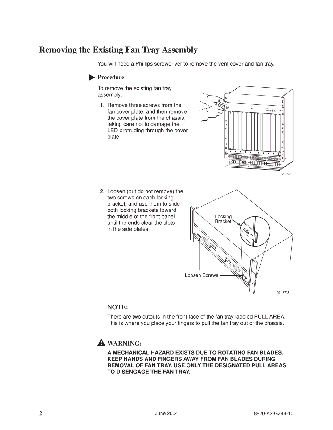
To remove the existing fan tray assembly:
1.Remove three screws from the fan cover plate, and then remove the cover plate from the chassis, taking care not to damage the LED protruding through the cover plate.
POWER | ALARMS | |
A | B | Fan Major Minor |
CLOCK SERIAL | AC |
|
|
|
|
|
|
|
|
|
| |
A | MCC | ALARM | 2 | 4 | 6 | 8 | LANA/WAN S1L0OT |
|
|
|
| |
|
|
| 12 | 14 | 16 | 18 | ||||||
CLOBCK SSEMRCIAML ALARM | 1 | 3 | 5 | 7 | 9 | B | 11 | 13 |
|
| ||
|
|
|
|
|
|
| 15 | 17 | ||||
2.Loosen (but do not remove) the two screws on each locking bracket, and use them to slide both locking brackets toward the middle of the front panel until the ends clear the slots in the side plates.
Locking
Bracket 
DO |
|
|
|
|
NCA |
|
|
| |
UNOTU |
|
| ||
U | DEP | I |
|
|
| T |
|
| |
SE RLACON |
| |||
| THTH E ! |
| ||
| PE E | FING |
| |
| ULL |
| ||
| DEFA |
| ||
|
| SIGTRER |
| |
|
| AR | NAAYS |
|
|
| EA | P | |
|
|
| STED | |
|
|
|
| AU |
|
|
|
| L |
|
|
|
| RL |
|
|
|
| E |
|
|
|
| A |
PULL
AREA
D
O
UNOCAUTIO
N
USDEPL
E R
TH H EN!
PUEDEFFIN
LLESANGE
ARIGNTRARS
E A Y
ASTED
Loosen Screws
NOTE:
There are two cutouts in the front face of the fan tray labeled PULL AREA. This is where you place your fingers to pull the fan tray out of the chassis.
!WARNING:
A MECHANICAL HAZARD EXISTS DUE TO ROTATING FAN BLADES. KEEP HANDS AND FINGERS AWAY FROM FAN BLADES DURING REMOVAL OF FAN TRAY. USE ONLY THE DESIGNATED PULL AREAS TO DISENGAGE THE FAN TRAY.
2 | June 2004 |