Verify the connection: the Lnk (link) LED on the
For further information refer to the Installation Instructions for each individual UIM model.
2.0IP DSLAM MANAGEMENT
The
3.0ADDITIONAL INFORMATION
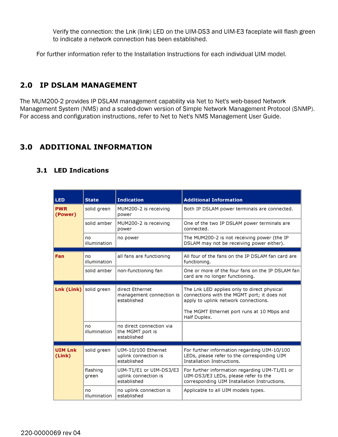
3.1LED Indications
LED |
| State |
| Indication |
| Additional Information |
|
|
|
|
|
|
|
PWR |
| solid green |
|
| Both IP DSLAM power terminals are connected. | |
(Power) |
|
|
| power |
|
|
|
| solid amber |
|
| One of the two IP DSLAM power terminals are | |
|
|
|
| power |
| connected. |
|
| no |
| no power |
| The |
|
| illumination |
|
|
| DSLAM may not be receiving power either). |
|
|
|
|
|
|
|
|
|
|
|
|
|
|
|
|
|
|
|
|
|
Fan |
| no |
| all fans are functioning |
| All four of the fans on the IP DSLAM fan card are |
|
| illumination |
|
|
| functioning. |
|
| solid amber |
|
| One or more of the four fans on the IP DSLAM fan | |
|
|
|
|
|
| card are no longer functioning. |
|
|
|
|
|
|
|
|
|
|
|
|
|
|
|
|
|
|
|
|
|
Lnk (Link) |
| solid green |
| direct Ethernet |
| The Lnk LED applies only to direct physical |
|
|
|
| management connection is |
| connections with the MGMT port; it does not |
|
|
|
| established |
| apply to uplink network connections. |
|
|
|
|
|
| The MGMT Ethernet port runs at 10 Mbps and |
|
|
|
|
|
| Half Duplex. |
|
| no |
| no direct connection via |
|
|
|
| illumination |
| the MGMT port is |
|
|
|
|
|
| established |
|
|
|
|
|
|
|
|
|
|
|
|
|
|
|
|
UIM Lnk | solid green | |
(Link) |
| uplink connection is |
|
| established |
| flashing | |
| green | uplink connection is |
|
| established |
| no | no uplink connection is |
| illumination | established |
|
|
|
For further information regarding
For further information regarding
Applicable to all UIM models types.